Close
0%
0%

Stylin' safety jacket.

I always feel like jackets needed more blinky sh*t. Now dreams become reality.

Similar projects worth following
Using my handy lil' Hackaday Trinket guy I am going to add some light up madness to a sweet not-leather jacket I found. It will be mostly be documented using my horrible cell phone camera, I don't have anything better, sorry. Oh also I find I am doing most of the write up on my phone at breaks at work so I must apologize now for all the typos heh...

Hey Everybody thanks for lookin' at my jacket I am making.

It is really a work in progress, I don't really have exact plans for it, other than to make it look awesome. I have a bunch of electronics bits and pieces laying around and I am just gonna see how far I can take this until the time runs out :D

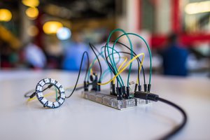
I thrifted the jacket at the goodwill and already all of the parts I have used so far. I plan on spending little to no money on it and as of yet, the Trinket was the most expensive part. I am very new to all of this, so I am probably going to publish what is most interesting to me, and if you want info on something I have neglected, please don't hesitate to ask about it.

The purpose of this jacket is to make me visible while riding at night, but more importantly to accomplish the difficult task of looking f*cking sick.

Plez enjoy, your friend,

✄✄✄✄✄✄✄✄✄✄✄✄

  • 1 × Hackaday.io branded Trinket chip thingy Its cool, USB n stuff..
  • 2 × HC74595 Shift Resgister I have seven but only used two so far
  • 5 × 100 ohm resistors I know, a little measley for current limiting but hey it works :D
  • 7 × S5880 Transistors High current General Purpose, used as a buffer to protect Trinkys lil' pins
  • 8 × 5 x 7 LED Matrix Display Can't find any docs on it, this pin configuration though: http://extremeelectronics.co.in/images/shop/led_dot_matrix_display_5x7_diagram.jpg

View all 12 components

  • Github!

    Scissorfeind03/28/2015 at 23:43 0 comments

    I added the codes to github in case anyone wanted to help me with the coding?

    https://github.com/scissorfiend/LED-Matrix-Thing/

    Thanks for lookin!

  • Super Stumped! Helps? :D

    Scissorfeind01/14/2015 at 06:01 2 comments

    Programming is hard for me, but I wanted to wait until after the contest to ask for help. For one piece of the jacket I wanted to create a set of modular matrix displays, each with with their own controller board and linked together by a ribbon cables. To the back of this I will add some kind of sealant and then a piece of Velcro to secure it to the jacket. I feel that this makes each display easy to adhere, remove and replace should one break. Please see my circuit below, presently it is built around parts I removed from various thrifted electronics.

    Note: Now that the contest is over I am considering breaking my own rule of using only free parts or things had at a thrift store. As you will see the way I am trying to organize the data is esoteric at best, and this is due to the way I have four displays spread across three shift registers, as opposed to giving each display its own shift register which would make coding much simpler. This is solely because I only had 3.

    I would like to create a system of stored character bit maps which can be used to make different words and controlled by a serial text string of 8 characters.. Right now I plan to have this string act as instructions for both the character on each Display and its position in a grouping of 8.This string will be processed by a separate function which will load the character map into the appropriate place in a String element, chopped and then shiftOut()'d. This String element would have 16 bits, the first 12 being each anode (plus 4 extra, presently unused) and the final 8 'activating' each of the 7 rows of cathodes plus 1 extra unused. I am planning on having each character map made of four frames due to the nature of the common cathodes of my displays, I feel this is the least amount of frames needed to display more complex letters like Q. I have seen code which lights up each pixel in a bit map individually, however that was with many fewer pixels. All four displays comes to 140 pixels controlled by 20 anodes, one for each column, and 7 common cathodes, one for each row.

    This is a pile of very rough mock ups for code which I barely understand. If anyone has any pointers about my overall approach or individual coding techniques, I am welcoming all criticism.

    Here is the code I am trying to use to calculate pre made character bit maps ( is that what you call them? ) into shiftable data. Right here I am just sending the data out to the serial monitor so I can play with the concept.

    String allOff = String(0b00000000);
    String allOn  = String(0b11111111);
    String halfOn  = String(0b10101010);
    //String arrayFun[4]  = { String(0b10101010), String(0b11111111), String(0b10101010), String(0b00000000) };
    String playVal  ;
    
    
    int ledPin = 13;
    
    byte rowData[4];
    byte colData[4];
    
    byte *charframe1Name[7] = {
    } 
    ;
    
    byte charAf1[7] = {
      B10000000,
      B00000000,
      B11000000,
      B00100000,
      B10010000,
      B00001000,
      B10000000 
    };
    
    byte charAf2[7] = {
      B01001000,
      B00000000,
      B00001000,
      B00000000,
      B01001000,
      B00000000,
      B01011000 
    };
    
    byte charAf3[7] = {
      B00001000,
      B00001000,
      B00001000,
      B00001000,
      B00001000,
      B00000000,
      B00000000 
    };
    
    byte charAf4[7] = {
      B00000000,
      B00000000,
      B11110000,
      B11110000,
      B11110000,
      B11110000,
      B11110000 
    };
    
    void setup() {
      Serial.begin(9600);
      Serial.print(F("Setup"));
      delay(100);
      pinMode(ledPin, OUTPUT); 
    }


    void loop() {
      while(!Serial.available()) {
    
        /* I want this part to eventually shift the array elements into a string
        for(int i = 0; i < 4; i++) {
         
         digitalWrite(ledPin, HIGH);
         Serial.print(F("playVal : "));
         Serial.println(playVal.toInt(), DEC);
         //int valJar = playVal.toInt();
         //Serial.print(F("valJar : "));
         //Serial.println(valJar, BIN);
         playVal += arrayFun[i];
         playVal += String("*");
         Serial.print(F("allOn : "));
         Serial.println(allOn.toInt(), BIN);
         Serial.print(F("i : "));
         Serial.println(i);
         
         Serial.print(F("length : "));
         Serial.println(playVal.length());
         
         delay(500); 
         digitalWrite(ledPin, LOW);
         delay(500);
         }
         */
       
     Serial.println(F(...
    Read more »

  • Bitshiftin'

    Scissorfeind12/17/2014 at 09:30 0 comments


    My initial test of my multiple display set up resulted in disaster: Don't hook up your ULN2003 with reverse voltage! Now it just spits out random oscillations on its outputs and such resulting in only one line lighting up. I might also not be understanding how my shiftOut() is working, the order of the bits and such.

    More tomorrow when I can get a new uln2003...

    Here is my code in case it seems like I am missing anything there?

    //Pin connected to ST_CP of 74HC595
    int latchPin = 8;
    //Pin connected to SH_CP of 74HC595
    int clockPin = 12;
    ////Pin connected to DS of 74HC595
    int dataPin = 11;
    int ledPin = 13;
    byte firstByte[] = { 8, 16, 8,16,8,16, 8, 16};
    byte secondByte[] = { 255, 255, 255,255,255,255, 255, 255};
    byte thirdByte[] = { 255, 255, 255,255,255,255, 255, 255};
    byte fourthByte[] = { 8,8,8,8,8,8,8,8};
    
    // { 0,0,0,0,0,0,0,0 }
    
    int sensorPin = A7;    // select the input pin for the potentiometer
    
    int sensorValue = 0;  // variable to store the value coming from the sensor
    
    
    void setup() {
      //set pins to output so you can control the shift register
      pinMode(latchPin, OUTPUT);
      pinMode(clockPin, OUTPUT);
      pinMode(dataPin, OUTPUT);
      pinMode(ledPin, OUTPUT);
      Serial.begin(9600);
    }
    
    void loop() {
      
      digitalWrite(ledPin, LOW);
        
        for (int i=0 ; i < 8 ; i++){
          digitalWrite(ledPin, LOW);
          sensorValue = analogRead(sensorPin);
          /*
          Serial.print(F("i"));
        Serial.println(i);
        Serial.print(F("First Byte"));
        Serial.println(firstByte[i]);
        Serial.print(F("Second Byte"));
        Serial.println(secondByte[i]);
        */
        digitalWrite(latchPin, LOW);
        // shift out the bits:
        shiftOut(dataPin, clockPin, MSBFIRST, firstByte[i]);  
        shiftOut(dataPin, clockPin, MSBFIRST, secondByte[i]);
      shiftOut(dataPin, clockPin, MSBFIRST, thirdByte[i]);
    shiftOut(dataPin, clockPin, MSBFIRST, fourthByte[i]);  
    
        //take the latch pin high so the LEDs will light up:
        digitalWrite(latchPin, HIGH);
        // pause before next value:
        delay(sensorValue);
        //digitalWrite(ledPin, HIGH);
        /*
        digitalWrite(ledPin, HIGH);
        delay(0.001);
        */
        }
        
    }


  • New Cool Junk n Stuff

    Scissorfeind12/17/2014 at 09:19 1 comment

    I have won a Bus Pirate in the random drawing contest! This is awesome because I have always considered buying one and coincidentally purchased one yesterday so I could try to interface with this neat thing I was given at work:

    Its a sweet Vizio Bluetooth Remote with QWERTY keyboard! I got it broadcasting as a Bluetooth device, now to find the pin...

  • On to two breadboards now...

    Scissorfeind12/11/2014 at 08:53 0 comments

    Only had a chance to wire it up, letters to com over the weekend.

  • LED Matrix Plan

    Scissorfeind12/10/2014 at 21:58 0 comments

    I have decided hoow to set up the Matrix displays and everything so it is easy to use and also repair. I am going to fabricate two boards which will hold 4 displays each as well as all of the required driver components so then I can essentially have them be modules I can hook straight into Trikles. Then I am.going to seal them epoxy or similar and use velcro to attach them to the jacket. This weekend I.might be able to make it out to The Legacy a sewing thrift shop in neighboring Sebastopol, they usually have all kinds of velcro.

  • LED Matrix Fun!

    Scissorfeind12/10/2014 at 09:23 0 comments

    I did more testing and was able to get the display to work POV style so I can get crazy with the patterns and text n stuff. Tomorrow I will work on getting multiple displays and actual text but for now, here are two videos I made to demonstrate the effect; One where I fail to demonstrate the principle, and a second where I fail to explain it.

    I have the LDR set up to control the speed of the display when flashing between two 'frames (?)' so you can watch the point where the two images blur together :D!

    Hear me explain it and almost roast my LDR:

    https://drive.google.com/file/d/0B4NTxdyFQRYlSXZYaUEwdV9UZFU/view?usp=sharing

    Watch it happen:

    https://drive.google.com/file/d/0B4NTxdyFQRYlVU92ekFGT1ZRdVk/view?usp=sharing

    Here is my code, again pretty much ripped from the Arduino website. One super important thing you can see is where I commented out all those serial messages, which are handy when debugging but take so much time they prevent you from flashing frames fast enough to confuse ya' brain. Another important part about this code structure is that it isn't really easy to make frames with, however it seems fine with me since I don't want to add more memory for too many animations and I like random patterns.

    //Pin connected to ST_CP of 74HC595
    int latchPin = 8;
    //Pin connected to SH_CP of 74HC595
    int clockPin = 12;
    ////Pin connected to DS of 74HC595
    int dataPin = 11;
    int ledPin = 13;
    byte firstByte[] = { 42,0,42,0,21,0,21,0 };
    byte secondByte[] = { 42,255,42,255,21,255,21,255 };
    
    int sensorPin = A7;    // select the input pin for the potentiometer
    
    int sensorValue = 0;  // variable to store the value coming from the sensor
    
    
    void setup() {
      //set pins to output so you can control the shift register
      pinMode(latchPin, OUTPUT);
      pinMode(clockPin, OUTPUT);
      pinMode(dataPin, OUTPUT);
      pinMode(ledPin, OUTPUT);
      Serial.begin(9600);
    }
    
    void loop() {
      
      digitalWrite(ledPin, LOW);
        
        for (int i=0 ; i < 8 ; i++){
          sensorValue = analogRead(sensorPin);
          /*
          Serial.print(F("i"));
        Serial.println(i);
        Serial.print(F("First Byte"));
        Serial.println(firstByte[i]);
        Serial.print(F("Second Byte"));
        Serial.println(secondByte[i]);
        */
        digitalWrite(latchPin, LOW);
        // shift out the bits:
        shiftOut(dataPin, clockPin, MSBFIRST, firstByte[i]);  
        shiftOut(dataPin, clockPin, MSBFIRST, secondByte[i]);  
    
        //take the latch pin high so the LEDs will light up:
        digitalWrite(latchPin, HIGH);
        // pause before next value:
        delay(sensorValue/10);
        /*
        digitalWrite(ledPin, HIGH);
        delay(0.001);
        */
        }
        
    }


  • LED Matrix & 595 Test

    Scissorfeind12/09/2014 at 08:50 0 comments

    Here is a link to the video of an LED matrix display cycling through patterns using code shifted to the 595's from the Trinket.

    https://drive.google.com/file/d/0B4NTxdyFQRYlalJTcllnOHJYWlE/view?usp=sharing

    At this point I am honestly not sure which bits are corresponding with which pins on the LED matrix, but I am about to actually pay attention to what I am doing and make a drawing. More to come, I hope to get text characters to display before the end of the night!

    Here is the code I am using, ripped off from the ShiftOut tutorial on the Arduino site:

    //Pin connected to ST_CP of 74HC595
    int latchPin = 8;
    //Pin connected to SH_CP of 74HC595
    int clockPin = 12;
    ////Pin connected to DS of 74HC595
    int dataPin = 11;
    int ledPin = 13;
    int outputVal = 127;


    void setup() {
    //set pins to output so you can control the shift register
    pinMode(latchPin, OUTPUT);
    pinMode(clockPin, OUTPUT);
    pinMode(dataPin, OUTPUT);
    pinMode(ledPin, OUTPUT);
    Serial.begin(9600);
    }


    void loop() {
    
    digitalWrite(ledPin, LOW);
    outputVal = 0;
    for (int i=0 ; i < 256 ; i++){
    Serial.println(i);
    digitalWrite(latchPin, LOW);
    // shift out the bits:
    shiftOut(dataPin, clockPin, MSBFIRST, i);
    shiftOut(dataPin, clockPin, LSBFIRST, i);


    //take the latch pin high so the LEDs will light up:
    digitalWrite(latchPin, HIGH);
    // pause before next value:
    delay(5); //extra fast for dazzlin'
    digitalWrite(ledPin, HIGH);
    delay(5);
    }
    
    }


View all 8 project logs

  • 1
    Step 1

    I started this project by going to thrift stores tirelessly looking for jackets I liked so I didn't have to sew my own, that may come later. I found one I liked and sparkled it up a bit, however I was not satisfied or caught in a grip of inspiration so I decided to take it further!

    I ride my bike to and from work everyday, and while I have a few lights already, you can never be too careful, so this is really a matter of life and death.


    Thus the idea was born, which is a hard step for me sometimes. ^.^

  • 2
    Step 2

    Next I shlumped through my cabinets of random e-junk and remembered I had nabbed this sweet LED clock with huge 7 segment displays! Check the photos of it.

    When I got it I was unable to power it however once I tore it apart I found it was meant to be driven with an AC power supply, which I dont think I even have....

    Once I had the badboy open I ripped off all of the parts, essentially everything I would need to drive the displays was already on the board, including a nice set of 7 SN74HC595 Shift Registers :D!

    There was also a handful of current limit resistors, high current transistors and a sweet looking LM2575 power IC which I have not looked into. The huge inductor (I think?) that was with it hints at some crazy current source setup, I want to learn more about that.

    So far all of the parts, displays and all are working great, I think I was simply ignorant of how to power it when I bought it.

    tldr: I ripped the clock apart...

  • 3
    Step 3

    Next I breadboarded up the shift registers to my Trinket and then to the matrix display. I used a handful of assorted transistors that were inside the clock for circuit protection, but I'll only post this circuit on request for two reasons: It seems this part of your circuit is going to be specific to your displays and I am going to be changing the circuit tomorrow to try out a nice ULN2003 instead of all these clunky TO-92's.

    I also added in my LDR sensor with a 10k for the other end of the voltage divider, gives me a nice range.

    Next I started shifting out random numbers using code I got from the internet which I didnt really read, however it confirmed that my circuit worked, watch my first video to see how it looked.

    After mapping out which bits would essentially 'activate' each anode and cathode line, I started sending out patterns of lines. To really test my theory I wrote up a script which would test out the POV action I would need to really get a sweet display.

View all 3 instructions

Enjoy this project?

Share

Discussions

Jasmine Brackett wrote 12/17/2014 at 18:50 point
Congrats on winning the random draw this week! http://hackaday.com/2014/12/16/trinket-edc-drawing-3-results/

  Are you sure? yes | no

PointyOintment wrote 12/09/2014 at 10:17 point
The deadline is in January. You can still enter. You just missed the first of the weekly project log mini-prizes.

  Are you sure? yes | no

Similar Projects

Does this project spark your interest?

Become a member to follow this project and never miss any updates