 Jac Goudsmit
Apple-1 emulator for SuperCon2018 Badge
I turned my SuperConference 2018 Badge Add-on board into a 6502 computer, so if you're tired of playing Zork on a Z80, you can play Super Star Trek on an Apple 1 emulator.
I didn't win the badge hacking competition, though I think I might have had a good chance to at least be admired on stage if I would have had 5 more minutes with a soldering iron; the add-on was basically working but it was disconnected from the badge because of a wiring mistake that I didn't notice until after all the soldering stations had disappeared.

Layout
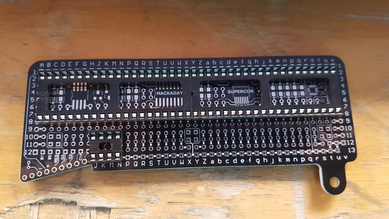
Fitting the Propeller and the Western Design Center W65C02S on the add-on board wasn't easy. The designers apparently didn't have two 40-pin DIP chips in mind when they made up how to connect the islands on the board. There was pretty much only one single way for the Propeller and the 6502 to fit on there, and I knew from the beginning that that would cause trouble, since the chips are right next to each other and everyone knows(?) that most DIP chips are too big to be mounted next to each other like that. There was going to be some filing in my future.
There was not enough space for the 8 pin DIP socket for the EEPROM after I had soldered the two 40-pin chips: it looks like there's an ocean of holes but they're all connected to each other or (by now) connected to the 40-pin DIP sockets. Fortunately the EEPROM has all pins 1-2-3-4 connected to ground, so I could cheat a little and just put it right there on the ground rail.
Propeller Bringup
The badge hacking area at the SuperConference had a nice supply of parts and tools, but unfortunately there were only 3 choices of wire: (1) Too thick and inflexible, (2) so thin that the wire strippers would cut the wire instead of stripping it, and (3) magnet wire.
I decided to go with magnet wire. I had never used that for a hacking project and I don't think I'll do it again. Basically the way you work with it is that you use the soldering iron to melt the insulation where you want to solder it, and this just seems like an incredibly unreliable way of working to me. I didn't have a multimeter to test each connection (I should have brought one, and I did the next day) so I had to eyeball each solder joint to guess if the wire was actually connected and if the insulation was (probably) gone. This made the soldering take a long time and I still found out later that I had one solder joint where the insulation hadn't melted.
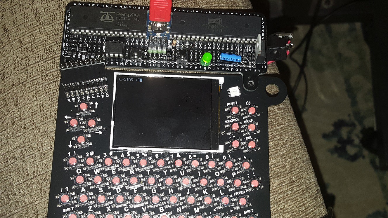
I soldered the pin header for the Prop plug on the board in a place where VSS would already be connected to the ground rail. I had to bend my 90 degree connector first; there was no way to mount it in such a way that I could have plugged in the Prop Plug from the side. Oh well.
The photo above is from when I had wired up the Propeller to the EEPROM and the Prop plug. The Badge was acting as power supply. Fortunately the Propeller Tool recognized the Propeller, or I would have aborted the project right there. But writing a program to the EEPROM didn't work at this time.
6502 Wire-Up
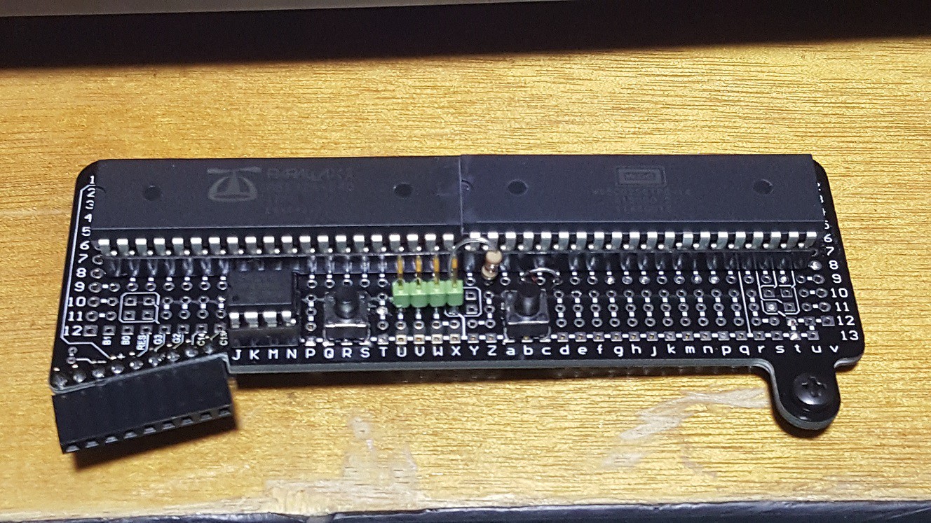
As I mentioned, the Propeller and the 6502 didn't fit in their sockets right next to each other. I was trying to scrape the edge off one of my chips with the beak of a side cutter, when another hacker noticed what i was doing, and was friendly enough to ask around for a file. I don't know where he got it and when I was done, he couldn't find the person he got it from, but thanks guys! After I had filed the sides of both chips flat, I could kinda jam them into their sockets.
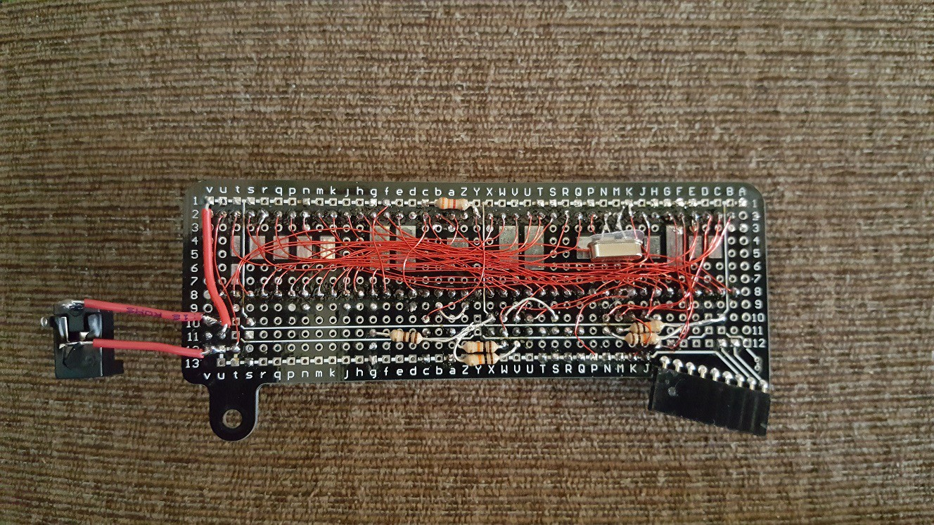
In the L-Star circuit, there are 26 connections between the Propeller and the 65C02S: 8 for the data bus, 16 for the address bus, and R/!W and the clock. There are also two reset buttons (one for the Propeller and one for the 6502).
There are also at least 2 pull-up resistors on the 6502 (one for !RESET and one for all the unused input signals !NMI, !IRQ, !RDY, !SO and !BE). The !RESET resistor went on the bottom but the other one went on top. The signal input pins on the 6502 are all two pins away from each other so I put the wire through the board and then "serpented" it back up and then back down. You can see it between the 6502 and the reset button.
"Final" wiring results
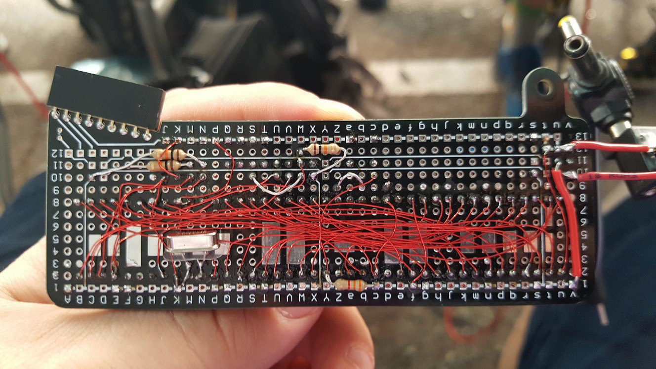
I already mentioned that the wiring was a lot of work, so let's not waste too much time on describing that, except to say I'm pretty proud of how it looks in the end.
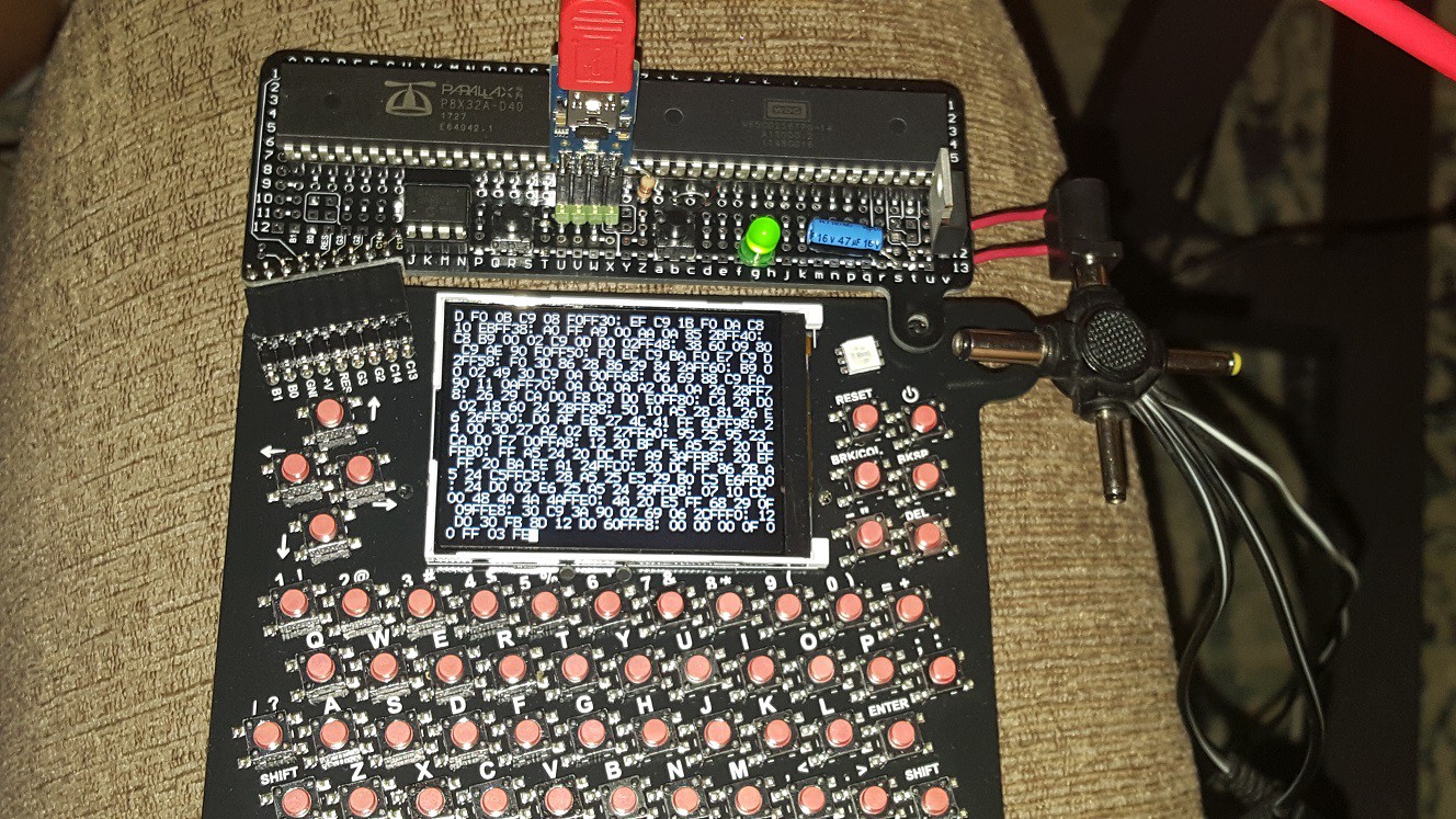
I was trying to figure out why the EEPROM wasn't working, and I thought maybe it was a power supply issue. The badge works on the unregulated power from two AA batteries (3V) and the Propeller is designed for 3.3V. I soldered a 3.3V regulator from my kit onto the board (with an electrolytic to prevent oscillating) and attached a barrel socket via some wires because I saw no way to mount it on the board in a way that would have made it stay attached. I also added a power LED because that way, if anyone asked me what I did with my add-on, I could at least say I added an LED ;-).
That didn't fix the EEPROM problem, but later on I realized that I had mounted the pull-up resistors for the 6502 but not the ones for the Propeller. The I2C circuit with the EEPROM really needs two pull-up resistors and if you want to detach the Prop Plug it's also good to have a pull-up attached to the Propeller reset pin. After I soldered those, I could program the EEPROM. Cool!
In the picture above, I think the only connections that I hadn't made yet were the connections to the serial pins of the badge.
Serial connection to the badge (log all the fails!)
By this time, it was Sunday afternoon and the time when the badge hacks had to be finished and submitted was coming closer. I had been in a workshop in the patio area and I knew there was not going to be another workshop there, so I stayed there and spent some time figuring the code that was in the badge. It looked like it already has most of a terminal emulator, which was used with the CP/M emulator. The code to read characters from the serial port and the UART receive-line and send it to the UART transmit-line and the screen was pretty simple and obvious, and it was also pretty easy to change my L-Star code so that it would use two serial ports instead of a serial port, a 1-pin TV driver and a PS/2 keyboard.
Unfortunately the patio got cleared, and I had to move once again. I found a place to sit in the SupplyFrame building but I couldn't figure out why the serial traffic wasn't working. Then I overheard another hacker say that he had worked on the serial port, so I asked for help. We thought I was overlooking something in the software but as it turns out, my software was okay and I had misinterpreted the schematic and connected my Propeller to the wrong pins on the connector (the two left ones instead of the two right ones). Of course by then the badge hacking part of the conference was about to begin and there was no soldering iron in sight anymore.
Software fixes
So I decided to go home and finish it there. The resoldering of the two wires was a 5 minute job (including getting my soldering station out; I don't have a workbench at home). I was happy to see that my simple terminal-program on the badge seemed to work, but it was spitting out garbage at first. As it turns out, when I modified the code on the Propeller to use 2 serial ports instead of video and keyboard, I had made a copy-paste error and it was programming the badge serial port at 115200 bps just like the Prop Plug serial port. Oops!
After I fixed it so it used 19200 bps for the badge connection, it kind of worked but the UART receiver on the badge got stuck: It displayed a few characters of the boot-up message of the L-Star program and then nothing. But the buttons on the badge were working fine (I could see that on the PC that was attached via the Prop plug). So I just had to slow things down a little bit so the UART on the badge wouldn't overrun.
My changes in the terminal driver of the L-Star firmware on the Propeller were pretty much copy-paste changes to do the same thing on the badge serial port as on the Prop plug serial port. At first I had changed the function that sends a string of characters so that it would send the string to one port and the to the other port. and when I changed it so it send the characters one-by-one, alternating between the connections, it started working!
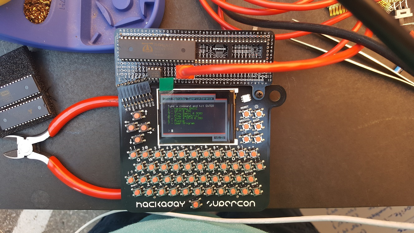
The Apple 1 was now being emulated (with 20KB of emulated RAM space, pretty cool for a computer from 1976), and I could enter commands from the badge keyboard. I could even enter a command that would generate a lot of output and the badge UART didn't get stuck!
Except... the badge and Woz Mon disagreed on when to go to the start of the next line. The badge's opinion was basically "never".
The firmware of the badge was written with C code in mind, so "\n" (line feed) causes the cursor to move to the beginning of the next line of the screen. But carriage return does nothing.
We could have a long discussion here about what line feed and carriage return are supposed to mean, and what character(s) should be used as line breaks.
The short and good is that the Parallax serial terminal uses Carriage Return as line break, and so does the Apple 1 software (Woz mon, Krusader and Woz BASIC as well as AppleSoft/Microsoft BASIC). So the solution was easy (though not ideal): make the Propeller translate all outgoing carriage returns from to line feeds before they get sent to the badge.
Hello Woz Mon! I'm a badge!

By the way, I posted a Pull Request to make the one-way terminal in the latest badge software into a two-way terminal yesterday. I also made some changes to my clone of the Supercon badge firmware so that it works more like a terminal: hitting Return (without shift) sends a Carriage Return (not a line feed), there now is a Caps Lock, and you can send all ASCII codes from the keyboard including the non-printable control codes. See https://github.com/JacGoudsmit/2018-Supercon-Badge.
Oh and by the way, I forgot to add a resistor on the RX line of the Propeller, so whenever the Prop plug was disconnected, the PIA emulator thought that it was getting garbage on the serial port to the PC. Sigh. So I had to get my soldering iron out of the garage again and solder one more resistor to my add-on board. Stupid 80-20 rule ;-)
So the above really is the final version of the add-on wiring.
Circuit description
The Supercon badge add-on version is the most basic form of the L-Star project. The Propeller is connected to the data bus, address bus, R/!W (Read/Not-Write) output and the clock input of the 65C02. It's also connected to the Prop Plug (basically an FTDI plug connected to the USB port of a PC) and the badge via two serial connections. And there's an I2C EEPROM that stores the Propeller firmware (which include the Apple 1 ROM). The following is a rough schematic of this minimal L-Star version (I made this on my phone, sorry if it doesn't pass ERC or sanity checks :-).

The Address Bus and Data Bus take up 24 of the Propeller's 32 I/O pins. An additional two pins are needed to provide the clock (PHI2IN) to the 65C02 and to get the Read/Not-Write (RWB) signal from the 65C02. The clock pin is the same pin as the SCL pin of the EEPROM; the SDA pin is held high during operation so that the EEPROM never gets enabled.
The Propeller generates a 1 MHz clock pulse for the 65C02, and at the beginning of each clock cycle, the 65C02 puts an address on the address bus, and makes the RWB line either high if it wants to read, or low if it wants to write. In write mode, the Propeller reads the data bus and in read mode, the Propeller writes the data bus; this happens during the second half of the clock pulse because during the first half (when PHI2IN is low), the 65C02 doesn't use the data bus.
On the 65C02, the input pins that can be used to interrupt the processor and to influence its operation, are all pulled high via a pull-up resistor. The Apple 1 doesn't use interrupts.
The reset pins on the 65C02 and the Propeller have a button to pull them down and a resistor to pull them up. There are also pull-up resistors on the I2C lines to the EEPROM (otherwise it won't work, see above), and on the RX line of the Prop Plug so that if you unplug it, the input will still be high so the Propeller won't see any incoming traffic.
Propeller Software
As you may know, the Propeller contains eight processor cores called "cogs" which each have a task. For example, one cog lets the 65C02 access the Propeller's internal memory to simulate ROM and RAM, another cog emulates the Peripheral Interface Adapter (PIA) chip, which on a real Apple 1 connects to the keyboard and to the video hardware.
There are two cogs that implement a serial port: one that's running at 115200 bps and connects to the PC via the 4-pin Prop Plug header, the other serial port connects to the badge at 19200 bps. Whenever the PIA emulator gets a byte from the 65C02 to send to the screen, it gets sent to both serial ports. And whenever the Propeller receives a byte from one of the serial ports, it gets sent to the PIA emulator, making the 65C02 think that a key on the keyboard was pressed.
65C02 Software
The 65C02 needs software to run, and the original Apple 1 came with only one small piece of software: Woz Mon. It takes up less than 256 bytes of ROM, and allowed you to inspect and change memory content, and execute programs. That doesn't sound like much, but it was enough to get started! Note: the Woz mon on board of the L-Star was slightly modified; keep reading.
A number of years ago, [Vince Briel] designed a replica of the Apple 1, and sold it online. He made some changes to the original design to make it more affordable. For one thing, there's no such thing as a 256 byte PROM anymore nowadays, so he had to use an EPROM and ended up with a lot of unused space. Plenty of space to add Integer BASIC (a BASIC interpreter by Steve Wozniak) which was originally available as a tape but modified to be used from a ROM.
Another addition was a program called Krusader by Ken Wessen. That program lets you interactively write 6502 and 65C02 code in a line-based editor (the Apple 1 had no cursor keys, it worked like a printing terminal) and convert them to machine language so it can be executed. It also includes a debugger. The Woz Mon code was changed slightly to make it possible to execute Woz Mon commands from Krusader. And Ken also made a change so that backspace works like a backspace. Thanks Ken!
Vince made the ROM image file available on his website, and I've been using it for years for the Apple 1 projects of the L-Star project.on Github. Thanks Woz, Vince, Ken and everyone else who contributed!
By the way, it's also possible to use the version of AppleSoft BASIC (really Microsoft BASIC) that was ported to the Apple 1 in recent years, by changing the ROM file in the Apple1.spin source file, and reprogramming the Propeller.
What's Missing
The circuit has a 64KB EEPROM which has 32K of unused space (the Propeller uses the low 32K) but there's no software on-board to use that space. I have some plans to use it in a certain way, but there are other things that have a higher priority. Also there's no other storage device on board. So how can you save programs?
For this, you have to think "outside the box" a little. Before we had SD cards, hard disks, floppy drives, tape drives etc. there were terminals with paper tape. You could enable the paper tape punch to record everything that was printed. And you could put the paper tape in the reader to pretend that you were typing everything that was on the paper tape. Similarly, if you want to save a program, you can go into Woz Mon and tell it to list a memory area, and record the output in the terminal emulator program that you're running on your PC. You can use the same program to send the output back to the Apple 1 after you restart it, because Woz Mon accepts its own output as input. Be gentle though: the Apple 1 wasn't very fast so even though the serial port with the PC runs at 115200, you should make sure your terminal emulator inserts delays after each character and (more importantly) after each line to give the 65C02 some time to process everything.
There's another problem: Woz BASIC does NOT accept its own output as input. Unfortunately it tries to pretty-print the listings to make them easier to read, and doesn't accept the pretty-printed listing from the keyboard. So you have to figure out where the program is stored in memory, and then use Woz Mon to dump the memory to the terminal emulator. This was done for several programs on the Brielcomputers forums. I know I found some information on how to do this on the Internet but I can't find it now. I recommend using the AppleSoft ROM file, because the Microsoft BASIC interpreter DOES accept its own output as input.
Conclusion
Making an L-Star in the form of a badge add-on was a fun thing to do. It would have been more fun if I could have gotten it done, and I blame the magnet wire for that. It took me way too much time to solder each connection and make sure the insulation had burned off.
While working on the badge, I get some inspiration for possible future projects. I also got some inspiration from comments that were left on Hackaday covering this (thanks again to Roger Chen). I hope this article inspired you too, to learn about L-Star and the 6502 and the Propeller and bitbanging buses and maybe other things.
Discussions
Become a Hackaday.io Member
Create an account to leave a comment. Already have an account? Log In.
Hehe, we both have the Woz Mon running on our badge :-)
Are you sure? yes | no
LOL that would have been an interesting thing to show the audience.
Are you sure? yes | no
Wow! Sorry to hear you were so close to finishing right at the end of badge hacking. This is such a delicious thing to cram into an expansion board and integrate with the badge. Great hack!
Are you sure? yes | no
Thanks! :-)
Are you sure? yes | no