Close
0%
0%

Shorty - short circuit finder

Short circuit finder, especailly for PCB checking

Similar projects worth following
When making home PCB or using cheap PCB services, you can end up with hair-like thin short circuit on the PCB, or even with good PCB you can make short circuit during the soldering... how to find it?

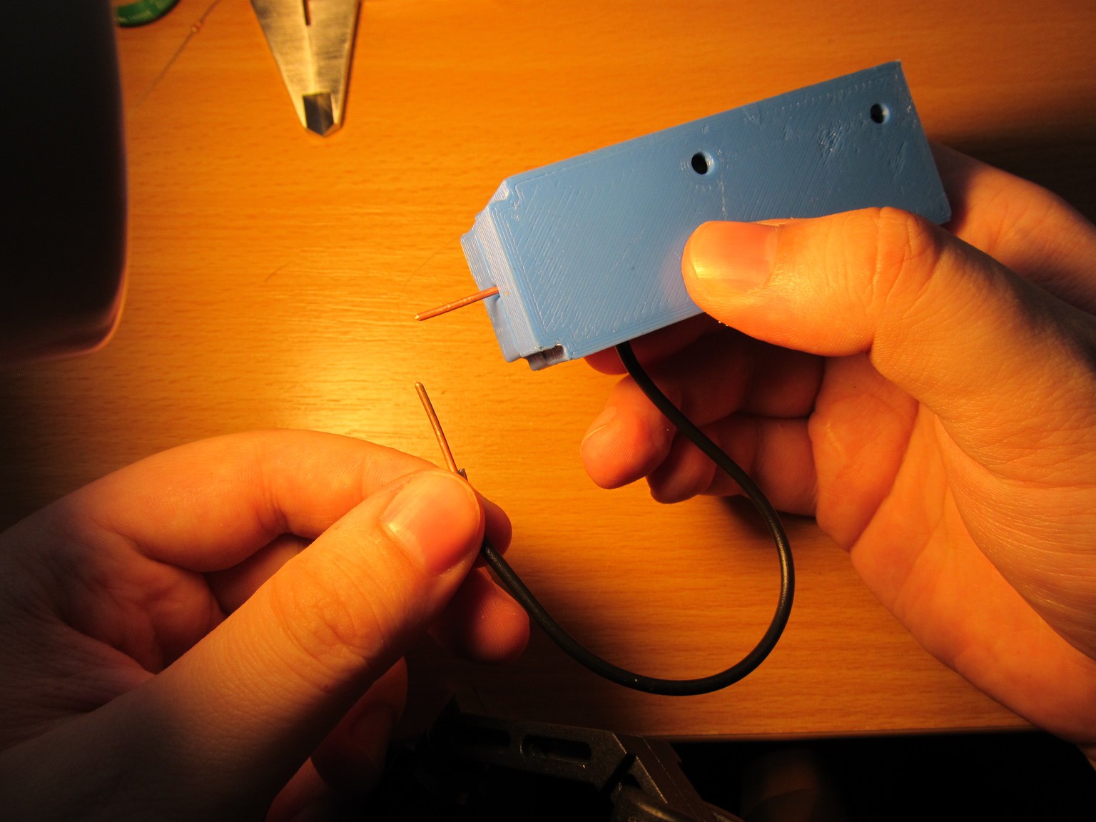
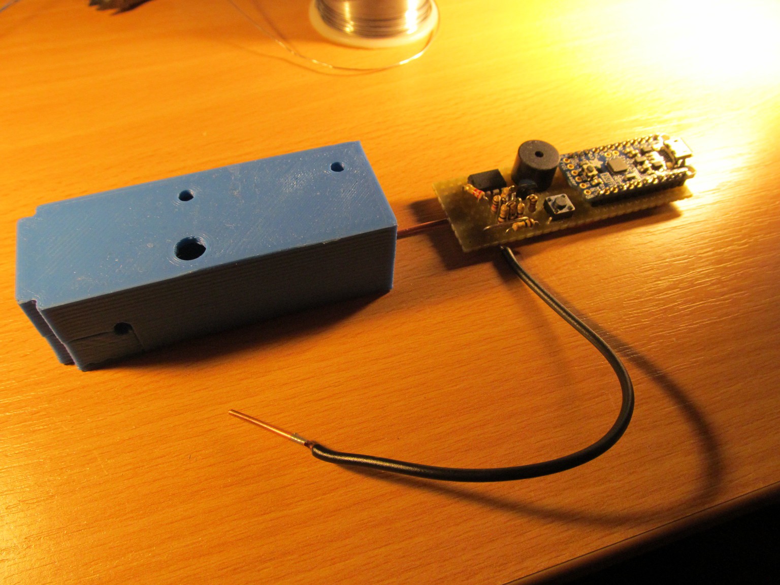
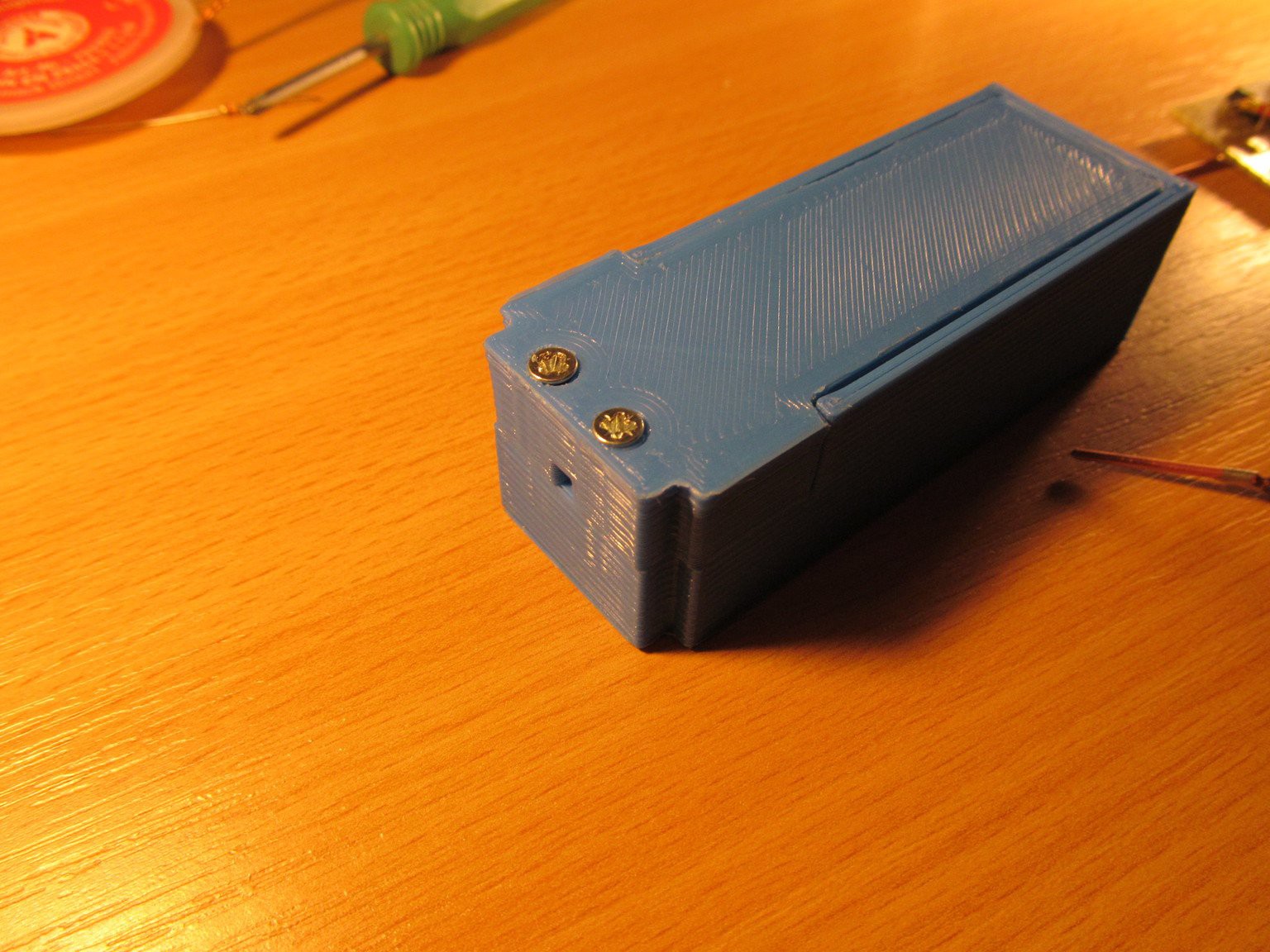
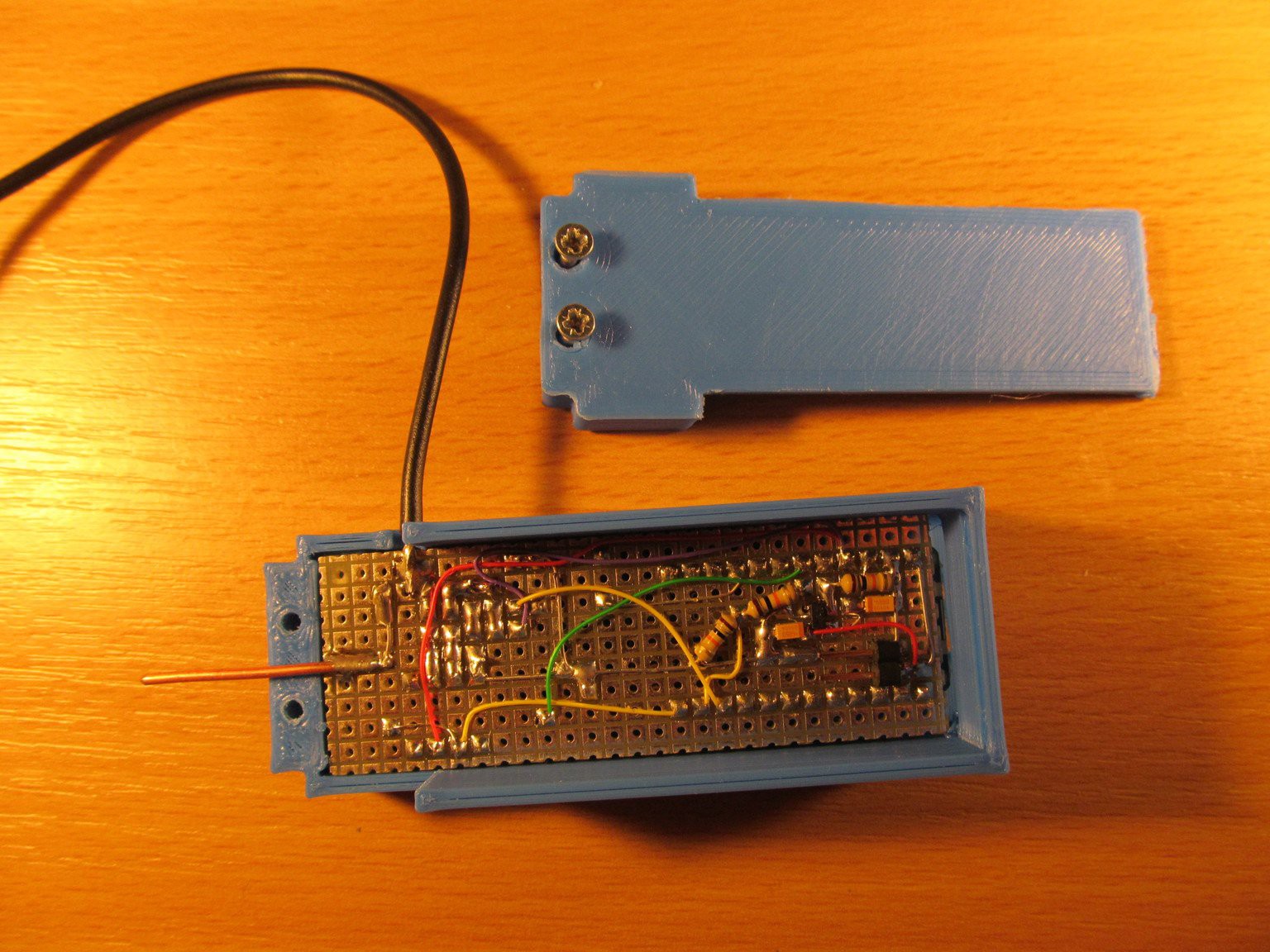
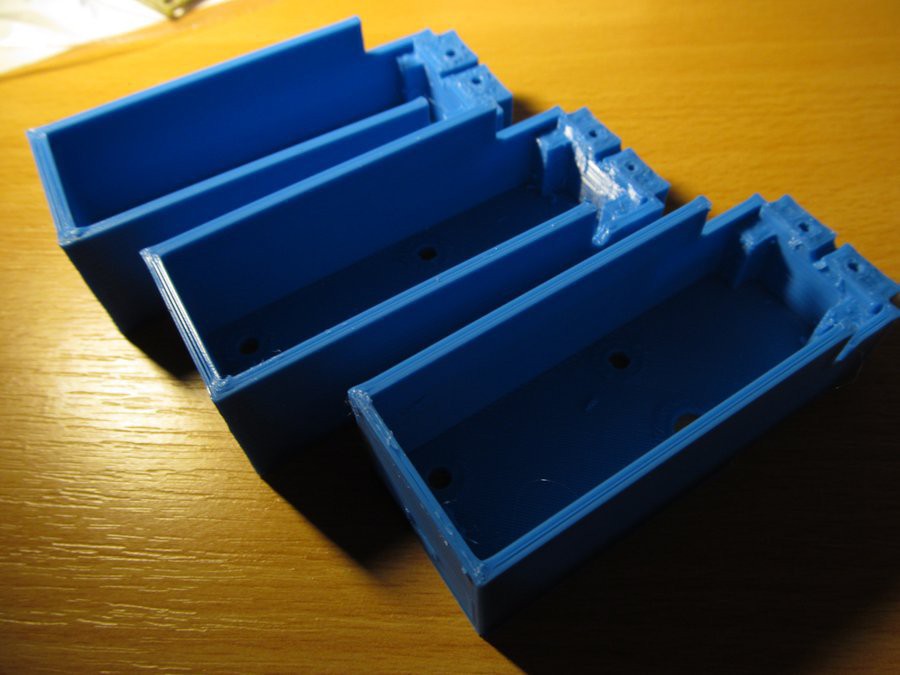
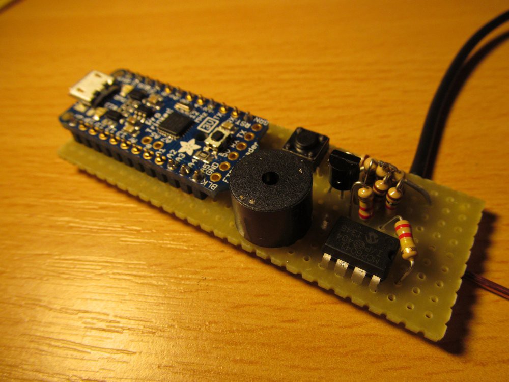
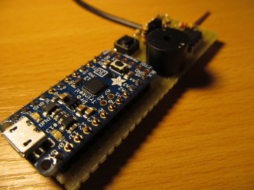
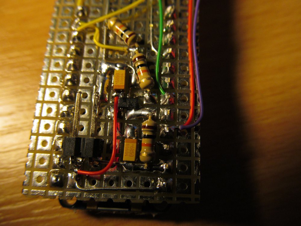
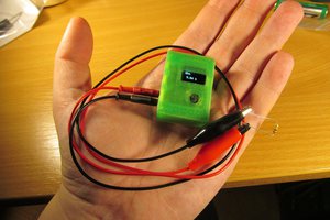
Shorty is short circuit finder, usable for checking PCB, for example. Where normal digital multimeters do not have enough of resolution to differentiate low PCB resistance in order of tens of miliohms to allow exact short circuit location, shorty comes to help. It is tiny (80x30x24mm), battery powered device, with option to charge the battery and load new firmware via USB. Current consumption is about 45mA when active, falls down to 6mA when idle for 15 seconds.

Want to build one?

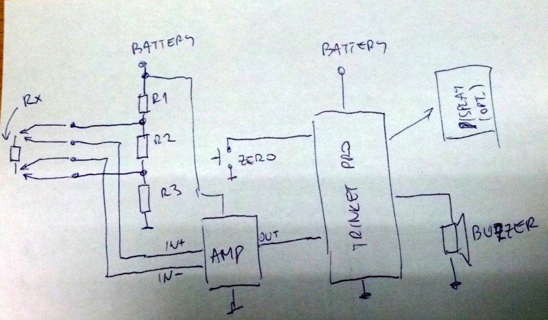
Take this schematics

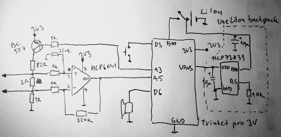
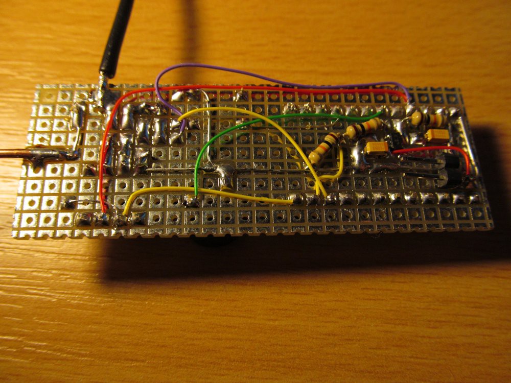
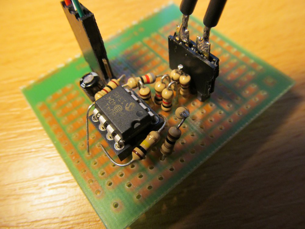
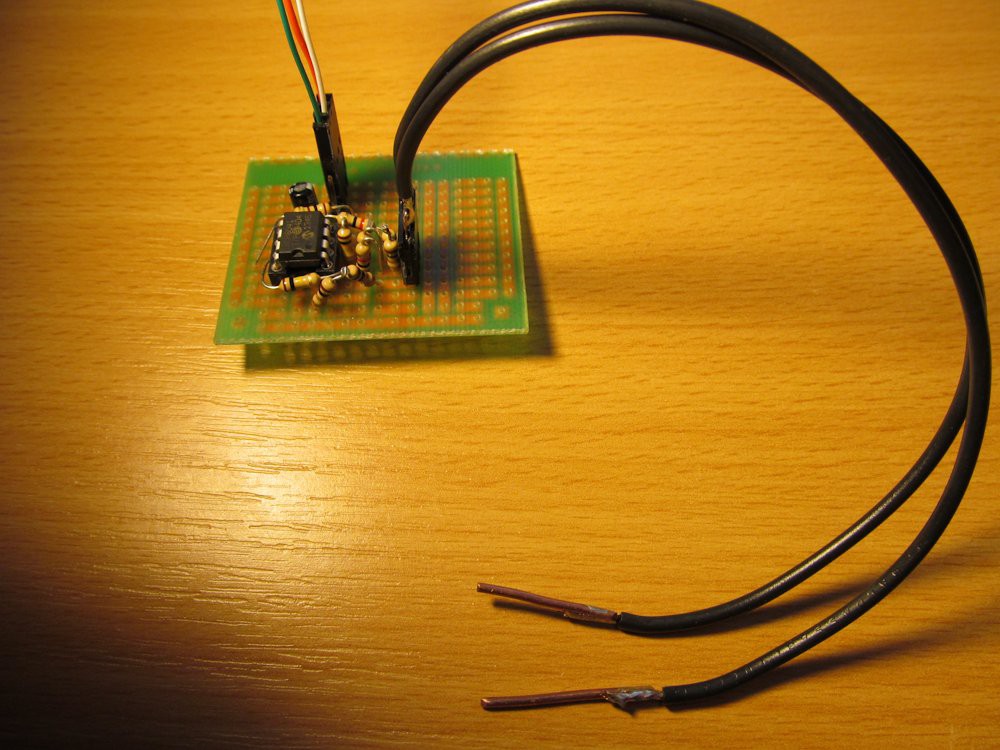
It is so simple I was lazy to prepare real PCB for it. Protoboard does its job just fine. If you don't feel like soldering the SOT23 MCP73831 device is what you want, feel free to replace it with Li-Ion backpack. The rest are normal through-hole components. For testing points I used piece of 1,5mm thick solid copper wire.

and load the firmware into Trinket pro via standard Arduino IDE.

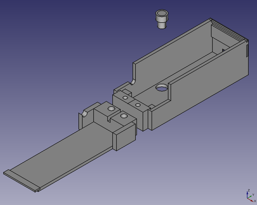
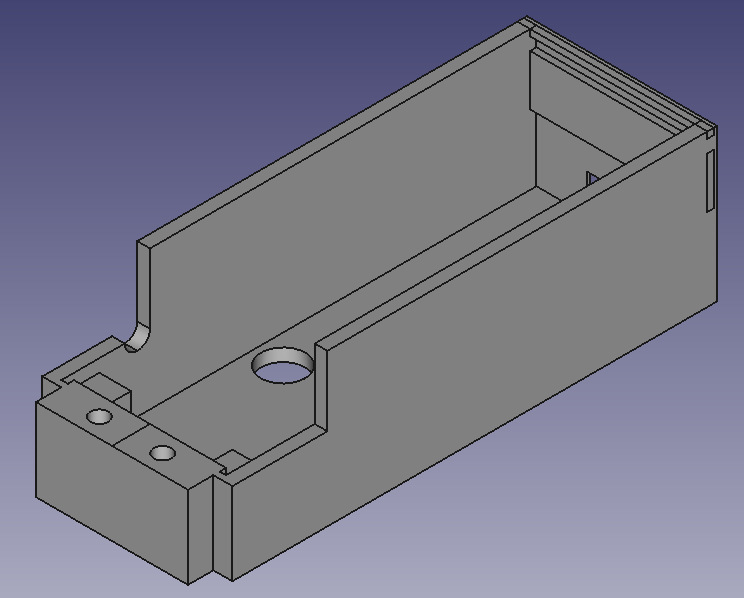
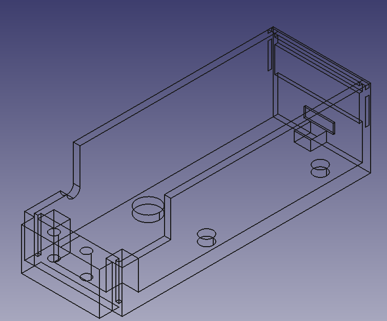
If you wan't, you can alter the design, as all the design tools I used for development of shorty are multiplatform and open-sourced - Xubuntu OS, Arduino IDE and FreeCAD.


  • 1 × Trinket pro
  • 1 × MCP6041 Amplifier and Linear ICs / Operational Amplifiers
  • 1 × BC557 Discrete Semiconductors / Transistors, MOSFETs, FETs, IGBTs
  • 3 × resistor 1k
  • 2 × resistor 220k

View all 16 components

  • 3D printed case, part two

    jaromir.sukuba01/03/2015 at 02:57 0 comments

    Today I printed case for shorty

    and made a little demonstration of its functionality


  • 3D printed case

    jaromir.sukuba12/29/2014 at 20:12 0 comments

    Honestly, this week I spent a lot of time on another projects, like pavapro, but this is getting to its finish too.

    I designed a case for shorty in FreeCad...

    ...and printed a few revisions of the case to found mistakes on each of them...

    and yet none of them is OK, though I'm getting closer and closer. I should get beter in 3D design.

    Regarding the software, I modified it to use the PNP transistor to switch off the resistor divider, so the current consumption can be lowered after a period of inactivity.

  • Things are getting real

    jaromir.sukuba12/23/2014 at 22:13 0 comments

    Today I put together the prototype. I used the same analog concept as discussed before. And this is how it looks:

    I opted to use only two probes, opposed to full 4-wire connection. From first tests it looks good enough - I'm able to discriminate as much as few as milimeters of copper 0,3mm (12mil) wide track on PCB.

    Closer look

    And here is bottom side of the board:

    With detail of MCP73831 in SOIC package

    Well, who doesn't feel to do this, can use adafruit LiIon backpak instead.

    I wrote first quick and dirty firmware for it and it looks quite usable. After some cleanup, I'll set up github repository for it. But before it, I'm going to heat up 3D printer and design some package for this gadget.

  • Input amplifier

    jaromir.sukuba12/21/2014 at 10:38 0 comments

    I protoboarded differential amplifier with opamp MCP6041 (I really love this opamp for low-power applications), with gain 100, resistors R1 = 82Ohm, R2 = 2Ohm, R3 = 2Ohm (see my previous project log) and put ordinary DMM on its output.

    When input of amplifier was shorted, I got expected reading a few milivolts - input offset voltage multiplied by circuit gain - with open output I got full output voltage, slightly under 4V supply. So far so good.

    Though the input has 4-wire connection to eliminate resistance of connactors and probes, I tried to make it simpler and used only two-wire probe, connected by 4-wire connection - eliminatiing the connector resistance, not probes.

    I also prepared simple probes with copper ends.

    Though not optimal setup, it works surprisingly good. When sliding the probes through copper track of PCB, the output voltage changed nicely with length and width of copper track - while DMM itself, switched to resistance measurement, showed just some random value around 1Ohm on the same tacks.

    So far so good. I'm going to attach trinket pro and buzzer.

  • First thoughts

    jaromir.sukuba12/16/2014 at 14:28 0 comments

    For detecting where short circuits actually is, you can theoretically use DMM, but most of the DMMs have problems with resistances below 1Ohm (mostly limited by simple two-wire probes) and do have only optical indication of the value (=you must jump your eyes between PCB and DMM), so it is not that great tool for exact localization of the short circuit.

    Having tool to distinguish between resistances in order of tens miliohms could enable me to find where the short circuit is. The tool doesn't have to have ability to display the exact value, only indication if the resistance goes down/up as I move electrodes closer to/further from the short circuit location. Sound indicator (buzzer) would be great for this, as I can fully concentrate my eyes on PCB, while beeping (low tone=low resistance; high tone=high resistance) would indicate the resistance.

    My first idea is something like this: three resistors (R1 mostly adjusts the measurement current, R2 limits the voltage on measured resistance; R3 produces slight voltage offset to allow differential amplifier to work correctly), differential amp itself (four resistors and opamp), trinket pro, buzzer, pushbutton (to allow "zero-ing" the "measurement") and optionally display.

    By the way, I feel like four wire method will not be actaully needed, especially when probes will not be detachable, but I have to make some experiments with this.

View all 5 project logs

Enjoy this project?

Share

Discussions

3rdnostril wrote 03/25/2021 at 22:04 point

hello,

I’m new here and I would very much like, to build this device. However, I’m a novice in electronics and I like chunky discrete components - I’m not interested in Arduino type devices. Is it possible to build the Shorty without a Trinket. If so, please let me know how. Thank you kindly

  Are you sure? yes | no

Bholanath Adhikary wrote 02/13/2019 at 09:03 point

Sir,please discuss software copy system. 

  Are you sure? yes | no

meestermole wrote 10/07/2018 at 14:09 point

i could REALLY use some help with this. I LOVE the idea of this project, I could use it to troubleshoot my arcade boards. Trouble is, I've completed Danjovic's port to tiny85, and i does not work for me. I get NO sound, and a weak light on the LED. I've tried to recreate this on a breadboard, still to no avail. I used an Arduino UNO with the 3.3v pin for power. With that, I just get a buzzing, and it pulses with the flashing LED. I used all 1% resistors. The only substitution i made was the transistor i used is a BC-327.  Any ideas?

  Are you sure? yes | no

Aqib Idrees wrote 12/03/2017 at 17:39 point

Did anyone port this to work with an ATtiny85 in the end? With compressed  library files  to work with the IDE?Keen to build one!

  Are you sure? yes | no

Josh Kittle wrote 06/20/2017 at 02:15 point

Has anybody got the tiny85 version of this working? I've made PCB's, assembled it, and I'm trying to compile the code, but I'm getting the same errors that Mehmet S. above was getting. I could use my nose pointed in a general direction.

  Are you sure? yes | no

meestermoley wrote 10/04/2018 at 21:02 point

I was getting those errors too - i've worked through it. I copied/pasted the code from the master.c file in the shorty-master.zip into my arduino IDE (i'm using an UNO as an ISP) - the problem now it that i have the whole thing built, programmed, etc - but it does nothing but blink the LED. It seems that interest in this project is gone...

  Are you sure? yes | no

meestermole wrote 10/07/2018 at 00:48 point

made PCB, assembled, compiled code, uploaded to tiny85 chip - and it doesnt do anything :\ - got enough to make 3 - going to breadboard it to rule out the PCB

  Are you sure? yes | no

Twong wrote 02/28/2017 at 23:32 point

Jaromir, in your original sketch the resistors in the input probe area are 1R, 2R, 82R but in your component list they are 10R, 20R, 820R. Which values did you really use? Tried looking at your photos but those resistors are not clearly visible in any of the images.

  Are you sure? yes | no

dido wrote 02/26/2017 at 11:20 point

That is nice! How its working, i want to make one with microchip pic? where i can read about the logic and the way it works?

  Are you sure? yes | no

Mehmet S wrote 02/05/2017 at 03:33 point

hi guys. I am interested  in this project and willing to make it for using repairing especially PC and Laptop motherboards.

I would like to make this with attiny85. So, Nikifena, could you pls make revision for attiny85 board schematics and diagram. Thanks very much to all you guys for your sharings.

  Are you sure? yes | no

[deleted]

[this comment has been deleted]

jaromir.sukuba wrote 02/05/2017 at 06:59 point

The only problem with connectors is they have some contact resistance, changing with time, use and other factors - that's why I used fixed probes with heavy duty wire. Your mileage may vary.

  Are you sure? yes | no

danjovic wrote 11/13/2016 at 19:31 point

Hi Jaromir. A new HAD challenge is coming, apparently for up to 1KB of code. I am sure that shorty will be a good entry!

  Are you sure? yes | no

jaromir.sukuba wrote 11/13/2016 at 19:44 point

Thanks. I noticed that, though the contest site returns just 404 for now. 1kB challenge seems like something for me. Recycling an old project in unchanged form is not my kind of entering the contest, I'd love to design something new or at least improve the old design.

  Are you sure? yes | no

nikifena wrote 10/30/2016 at 21:20 point

Here is my idea implemented into a Attiny328:

It's much better to implement this idea into a smaller ucontroller.
If you guys like, I will redraw the schematics for tiny85

EDIT: A 100k resistor must be added between the gate and the source of the mosfet :)

  Are you sure? yes | no

Mehmet S wrote 02/05/2017 at 03:39 point

hi guys. I am interested  in this project and willing to make it for using reapiring motherboards.

I would like to make this with attiny85. So, Nikifena, could you pls make revision for attiny85 board schematics and diagram. Thanks very much to all you guys for your sharings.

  Are you sure? yes | no

nikifena wrote 10/30/2016 at 09:05 point

Pretty nice project gyus! I like it

I'm not fimilar with ucontroller programming, but adding the project into a attiny45 will be great! Another hardware improvement can be a mosfet for powering the unit. After some time - 5 minutes for example, the mosfert turns off the voltage to the controller and there will be no current loss.

I have good experiance with pcb design, so if someone make it smaller, I can make nice pcb for this project.

@danjovic
Did you fit the code into a attiny45?

Thanks

  Are you sure? yes | no

danjovic wrote 10/30/2016 at 12:32 point

Yeah, but haven't tested yet, since I am away from home now.  Did some PCB work on a Tinyx5 version also: https://hackaday.io/page/2420-shorty85 . The code and PCB can be found at my github fork: https://github.com/Danjovic/shorty

  Are you sure? yes | no

nikifena wrote 10/30/2016 at 14:41 point

If you like, I will make smd pcb with a charger and I will show you.
My idea was to disconnect the positive pin from the circuit with a mosfet. When you press the power button, it powers the unit and the ucontroller turns on the mosfet for some time.

  Are you sure? yes | no

Mehmet S wrote 02/25/2017 at 20:37 point

Hi, I am trying to upload (burn) shorty to attiny85 kickstarter clone module via USB, but when I try to compile it on Arduino IDE it gives error like this ;

shorty:27: error: 'UBRR0H' was not declared in this scope


   UBRR0H = ((_UBRR) & 0xF00);

this is the first line in main function!  I use IDE version 1.8.0 on win7 32 bit.

  Are you sure? yes | no

danjovic wrote 10/31/2016 at 15:08 point

An SMD version would be great too...
About the button in yout schematics I think it should be connected to PD3 instead one of the anodes of Diode D3.

  Are you sure? yes | no

nikifena wrote 10/31/2016 at 15:15 point

Not sure how the core works. Yes, if this is the power button. As I understand the controller turns On the transistor when the unit starts. I use this zero voltage as control power voltage. I'm not sure what's the function of the PD3 in the original design.

  Are you sure? yes | no

danjovic wrote 10/15/2016 at 07:43 point

Hi Jaromir

I've been porting this project to an ATTiny45. The code is mostly C after all.
I think the power consumption may be reduced by turning on the transistor and sampling the voltage at given intervals driven by an interrupt.

Have been working also on a single sided board for the project. 

  Are you sure? yes | no

jaromir.sukuba wrote 10/15/2016 at 12:14 point

Yep, the transistor is here to be switched on and off. I'm looking at the code again and it is rather simplified (read as messy). Magic numbers all over the shop, it could take a lot of #define statements and functions encapsulations.

Feel free to improve it :-)

  Are you sure? yes | no

danjovic wrote 10/15/2016 at 13:26 point

I did most of the #defines already, including .h files for either Atmegax8 and Tinyx5. Have to test it though.

  Are you sure? yes | no

danjovic wrote 10/06/2016 at 16:25 point

That's ingenious, Jaromir. I don't know how I've never seen this project before!

  Are you sure? yes | no

Larry wrote 10/06/2016 at 06:56 point

I'll probably put it into a small project box with banana jacks and use with a pair of dmm probes so I can use some pressure on the probe tips if needed.  I can also file the probe tips to needle point.  Great project you put together!

  Are you sure? yes | no

jaromir.sukuba wrote 10/06/2016 at 08:30 point

It's better to have fixed probes, in order to avoid contact resistance of banana jacks. It's resistance is in the same order of magnitude of resistance you want to detect. But anyway, contact resistance problem is a bit of magic, so your mileage may vary.

  Are you sure? yes | no

Larry wrote 10/06/2016 at 18:27 point

Good point! ,,,no pun intended. Maybe I will solder the probe leads to the board and make the probe wires a bit shorter than original. Keep up the great work!

  Are you sure? yes | no

Similar Projects

Does this project spark your interest?

Become a member to follow this project and never miss any updates