William
The thing I must emphasize the most when tackling a project like this: make the time-consuming circuit-boards easy to remove. It is much better to labor over a project at a standing workstation than hunched over the floorboard of your truck. The actual installation was a fairly speedy process.
"The first step was to re-wire a string of 120VAC Christmas lights for 12VDC."
I divided the string in half (cut where there are only two wires) and followed a guide which creates a number of parallel circuits along each string of lights. I found 12VDC per five lights was ideal. Each string draws between one & two amperes. I got the setup working, but promptly burnt out one of the two circuits in the trailer lighting module. Since I was not as confident as I am now with micro-controllers, I opted for a relay-based approach in 2013. This kept the load off the new trailer light module & added some flexibility to my circuit. I discovered that I could dim the lights (making them running lights, essentially) by lifting the normal ground from both strings & sending the 12V through the combined string. This functioned quite well, but felt stapled-together. I wanted more control.
"I realized I needed to go digital."
I decided the Arduino must consume NO power while standing by. I'll get to that in a bit.
"This almost led to the project being scrapped until next year."
I lost quite a bit of time dealing with regulated power distribution & clean I2C communication. I was able to finally solve these problems around Dec 10th, 2014 and complete the installation process.
How it works:
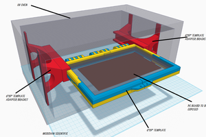
There are three enclosures installed in the truck. One under the hood, one under the driver's seat, and one in a compartment in the truck bed. The lights were installed on a truck lid, but can be installed along the bed via rain-gutter Christmas light clips. There is an MCP23008 I2C port expander under the hood which the Bluetooth-enabled Arduino (BLEduino) in the cab communicates with. The port expander has eight GPIO pins. Six of those pins, currently, read the status of various 12VDC lines via a set of opto-isolators. One other pin is being used for system power control.
There is a master relay which can have its coil charged via two sources: 12VDC controlled via pin 8 of the MCP23008, or 12VDC from the right blinker. When the truck is unlocked, both left & right blinkers trigger twice. This momentary input from the blinker is enough time for the Arduino & MCP23008 to initialize and take over power control. From there, the Arduino starts a timer which powers everything off when complete. This is ideal, but the system needs to stay up while the truck is running. The Arduino also monitors the truck's ACC line. If that is high, no countdown occurs.
The lights are controlled via two pins capable of pulse width modulation. Two transistors in the truck bed enclosure handle the heavier loads. These get rather warm. Heat sinks have been added. I am considering changing those to MOSFETs some time next year. Given this part of the system will only be used in the colder months, its not much of a priority for me. When I remove the lights (with ease) in a few weeks, the rest of the system will remain.
 fl@C@
fl@C@
 Inderpreet Singh
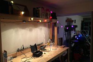
 Scott F