 Nick Sayer
There are two variants of the Hydra. One is the "splitter" variant. It has a J1772 inlet and two plug/cable sets. It was the original version of the Hydra. The other variant is the "EVSE" variant. It trades the J1772 inlet for a simple AC power cable. To be compliant with the standards, the EVSE variant has a GFCI for safety (the splitter doesn't because the host EVSE is assumed to have one). The EVSE variant also has a clock/timer chip and the firmware has an event system to facilitate allowing EV charging to happen only when electric rates are lowest.
Both variants offer two different operating modes. In "shared" mode, the rules are that if both cars are requesting power, each will be allotted half of the power available (the available power is indicated by the host EVSE for the splitter variant, and is a user configuration parameter for the EVSE variant). When one car finishes (or if only one car is connected), then that car is allowed full power. In "sequential" mode, only one car is allowed to charge at a time. When the charging car finishes, the opportunity to charge will be offered to the other car. The benefit of the Hydra is that the plug doesn't have to be manually moved from one car to the other (potentially at 2 AM for ToU charging).
Sensing the amount of available power (for the splitter variant) and informing each car of the available power is done via a signal wire within the J1772 cable called the "pilot." The EVSE indicates its availability by presenting a +/- 12 volt 1 kHz square wave on the pilot line with a 1 k-ohm impedance. The duty cycle of the square wave is the indication of the ampacity of the EVSE. The car accepts this offer by loading the pilot line with a particular resistance value in series with a diode to ground. The two most common resistor values are 2.7 k-ohm and 882 k-ohm (or 1.3 k-ohm in parallel with the 2.7k-ohm). The 2.7 k value indicates the presence of the vehicle. It will bring the 12 volt pilot down to 9 volts (due to the 1 k source impedance). The diode will prevent the resistor from impacting the negative portion of the square wave, which will remain at -12 volts. This is an important safety feature that allows the EVSE to distinguish between a vehicle and a bucket of salt water that has JUST the right resistance. Adding 1.3 k-ohms in parallel with the 2.7k will drop the voltage down to 6 volts. The host EVSE monitors the voltage of the pilot output to detect these state changes from the vehicle and turn the power on and off.
The UL specifications for charging stations require a number of safety systems, and the Hydra makes every attempt to include them all. These include:
- A GFCI circuit - stops charging instantly if residual current leakage is detected in excess of 20 mA. This is present only on the EVSE variant (the splitter variant relies on the presence of a GFCI in the host EVSE).
- A ground impedance monitoring system - stops charging if current flow to the system ground is not possible, or excessive impedance is detected.
- A relay status test - checks to insure that voltage is present on the J1772 output side of the contactors if and only if the contactor is actively engaged.
The instructions here are for both the version 5.x Hydra EVSE and splitter variants.
Theory of operation
Follow along with the schematics in order to see what's going on. Each section will reference a different page of the schematics
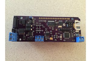
HV board
The HV board has 4 jobs:
- Provide 5 VDC power for the logic/display board
- Perform a GCM (ground continuity monitor) test to insure the path to ground is functional.
- Perform a relay test to insure that there is power on the load side of each contactor if and only if that contactor is engaged by the firmware.
- Switch the contactor power on and off for each car.
The 5 VDC power is provided by an isolated power supply module. It can provide up to 5 watts,...
Read more »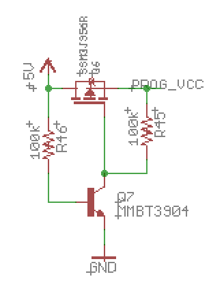


 robert.c.baruch
 The Big One
 Bharbour
I purchased one a couple years ago and finally got it put together but I am not having any luck. Side A gives a GFI error half the time I connect a vehicle, the other half of the time charging just never starts even though the vehicle can see available amps. I have verified connection from pilot pin to Hydra board. Side B will give a GFI error half the times a vehicle is connected and will actually charge sometimes, but gives an overcurrent error (18A on 16A pilot) when only 16 amps are actually being pulled. I've rebuilt the thing twice following instructions to the T but getting the same results. Any advice?