 Evan Li
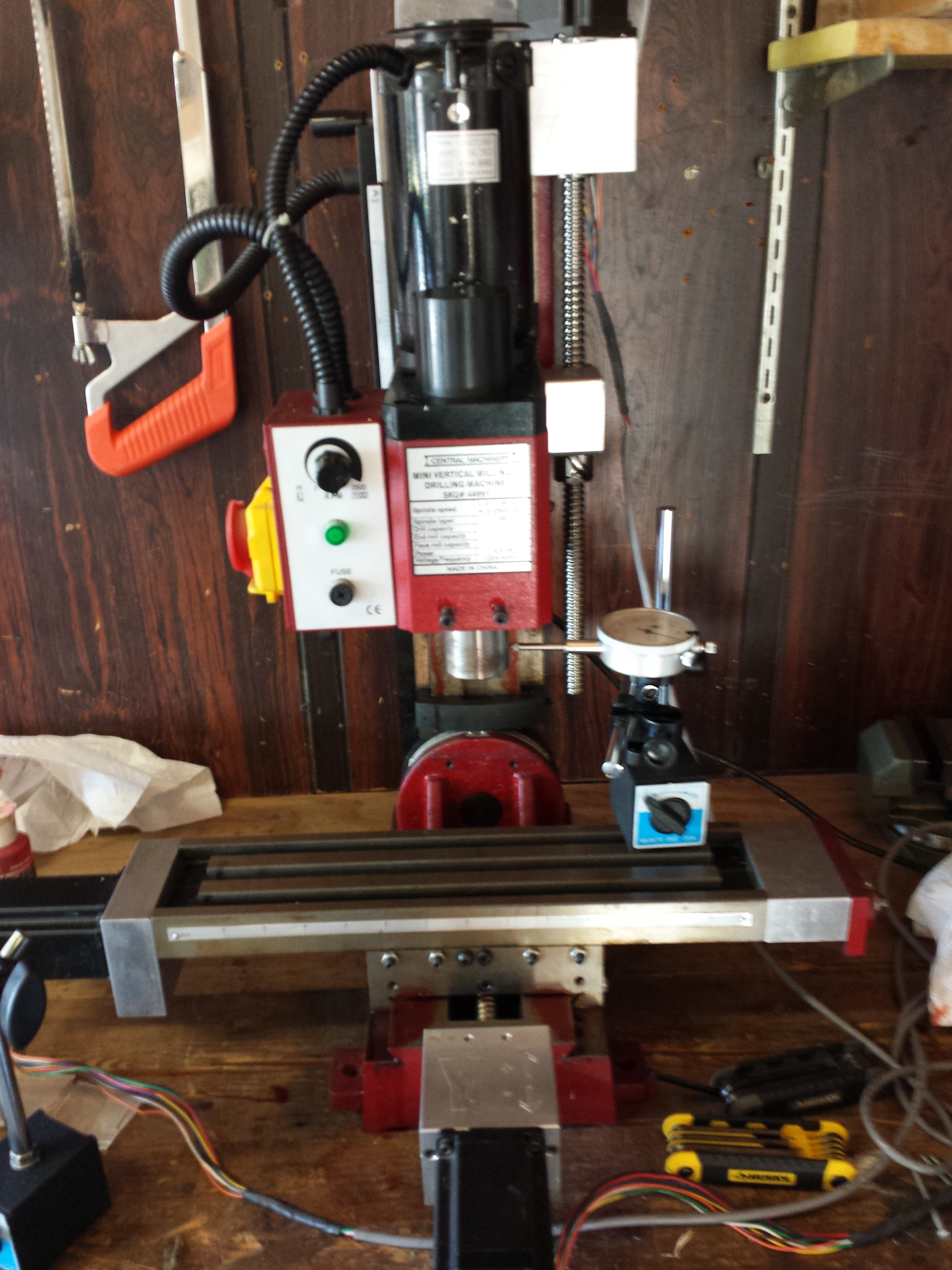
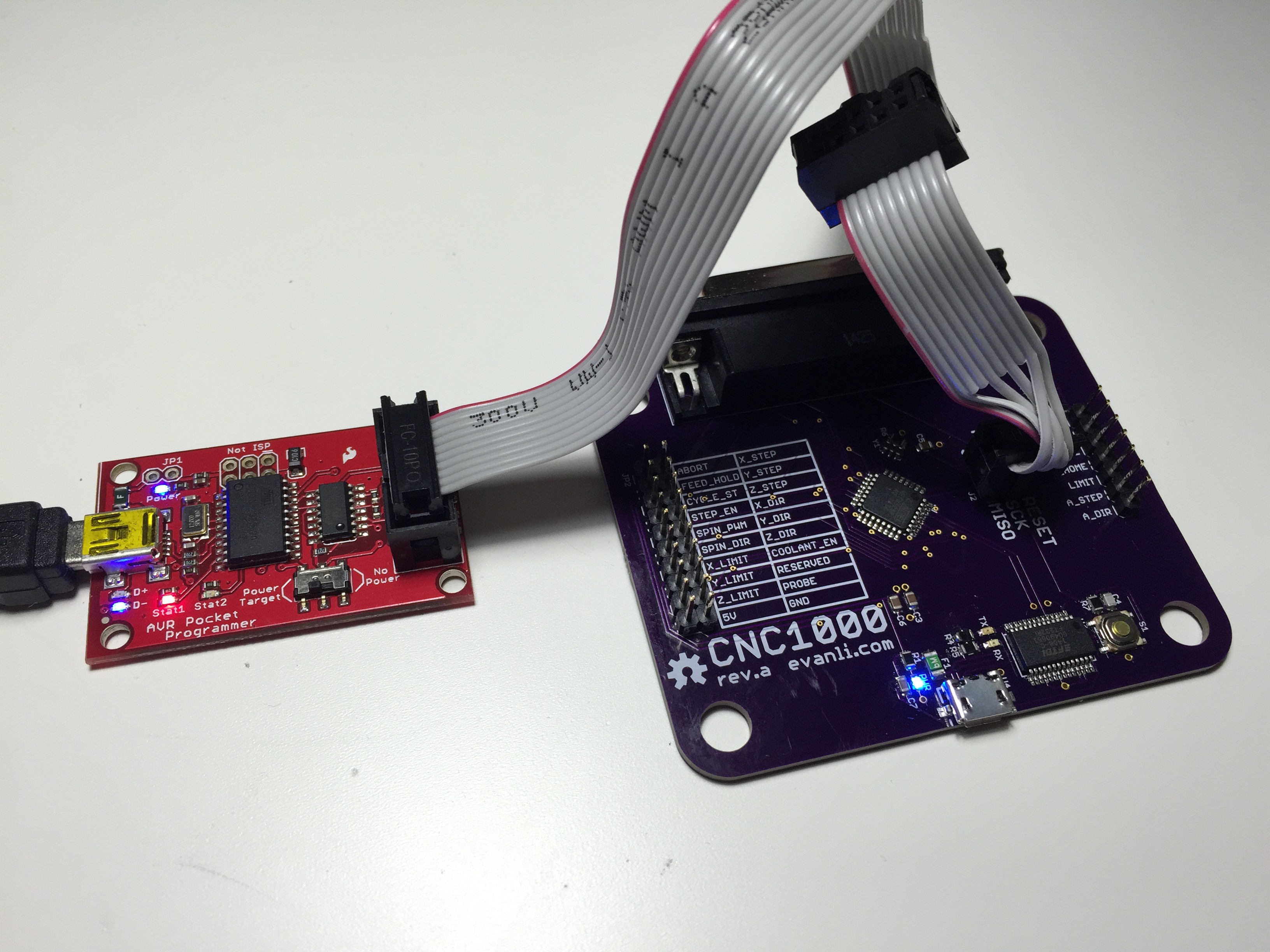
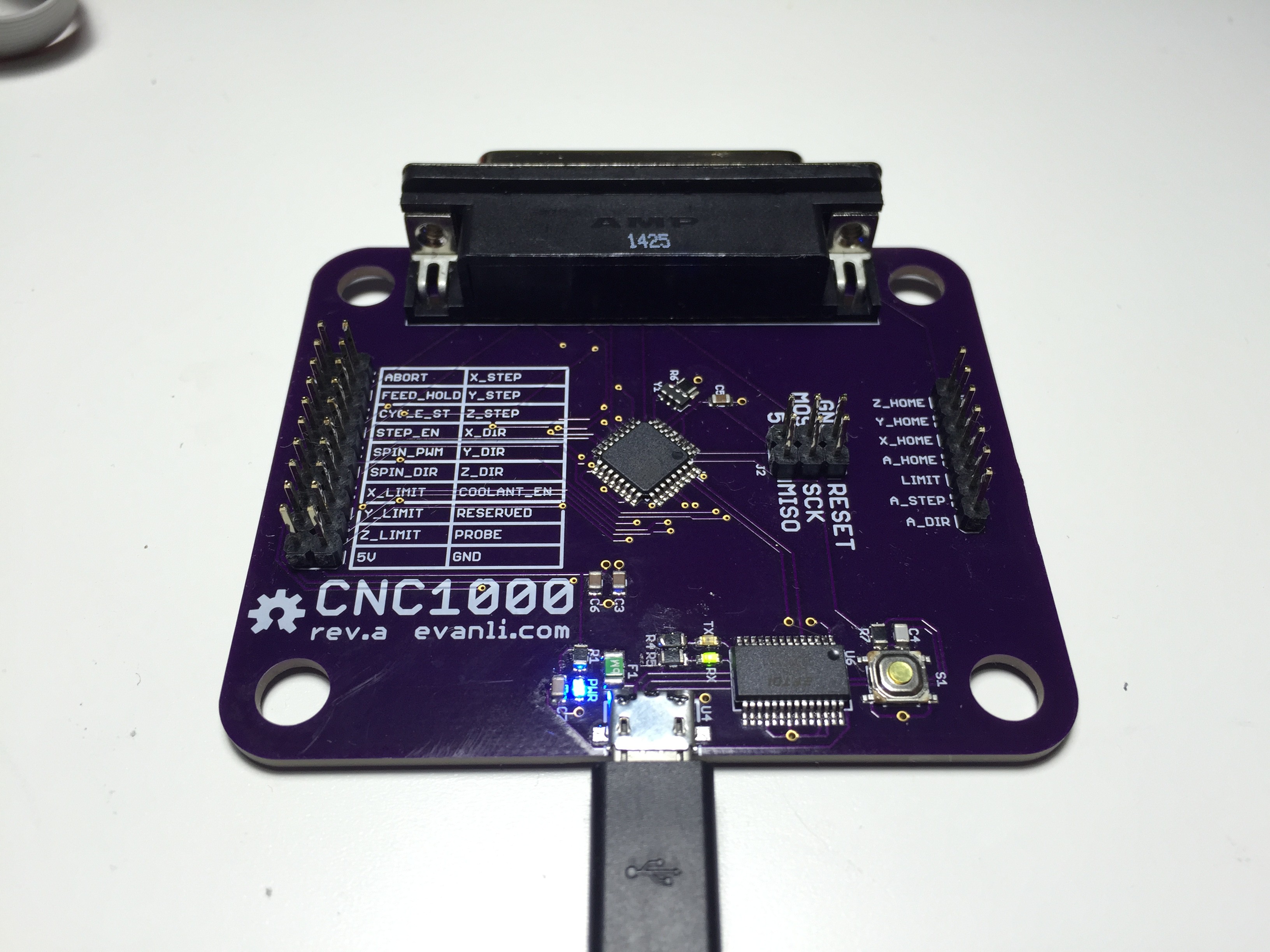
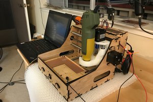
The plan is to replace the parallel port interface on the stepper driver with a microcontroller running GRBL. The mill can than be run from a USB interface on any computer rather than a increasingly rare parallel port. Also planned are some incremental upgrades to the hardware on the mill, such as spindle control, and a flood coolant system.
0%
0%
Servicing and Upgrading a Harbor Freight Mini Mill
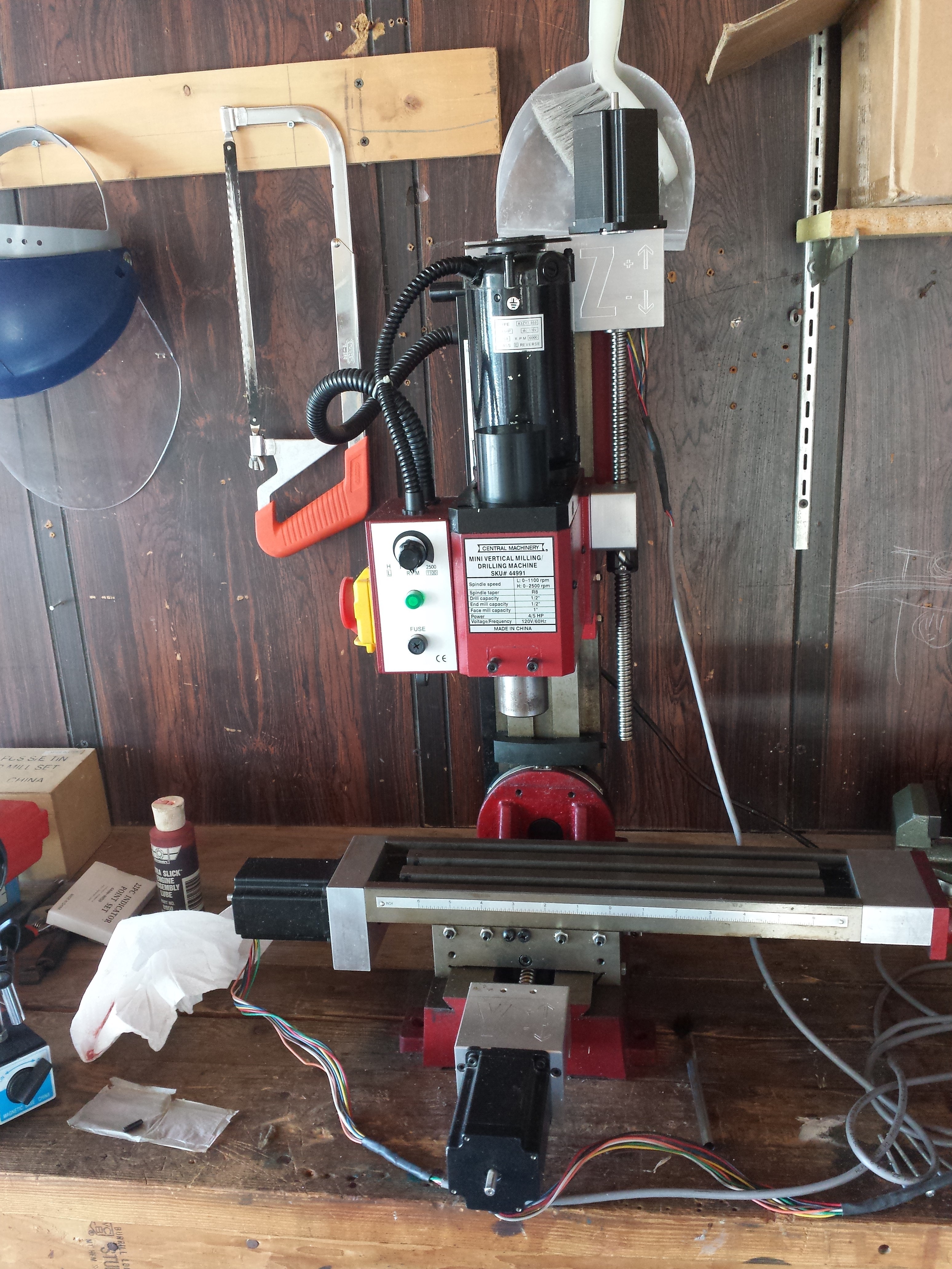
Years ago, I converted a Harbor Freight mini mill to a CNC using a CNCFusion kit and stepper controllers from HobbyCNC. Time to fix it!
Become a Hackaday.io member
Already have an account? Log in.
Just one more thing
To make the experience fit your profile, pick a username and tell us what interests you.
Pick an awesome username
hackaday.io/
Your profile's URL: hackaday.io/username. Max 25 alphanumeric characters.
Pick a few interests
Projects that share your interests
People that share your interests

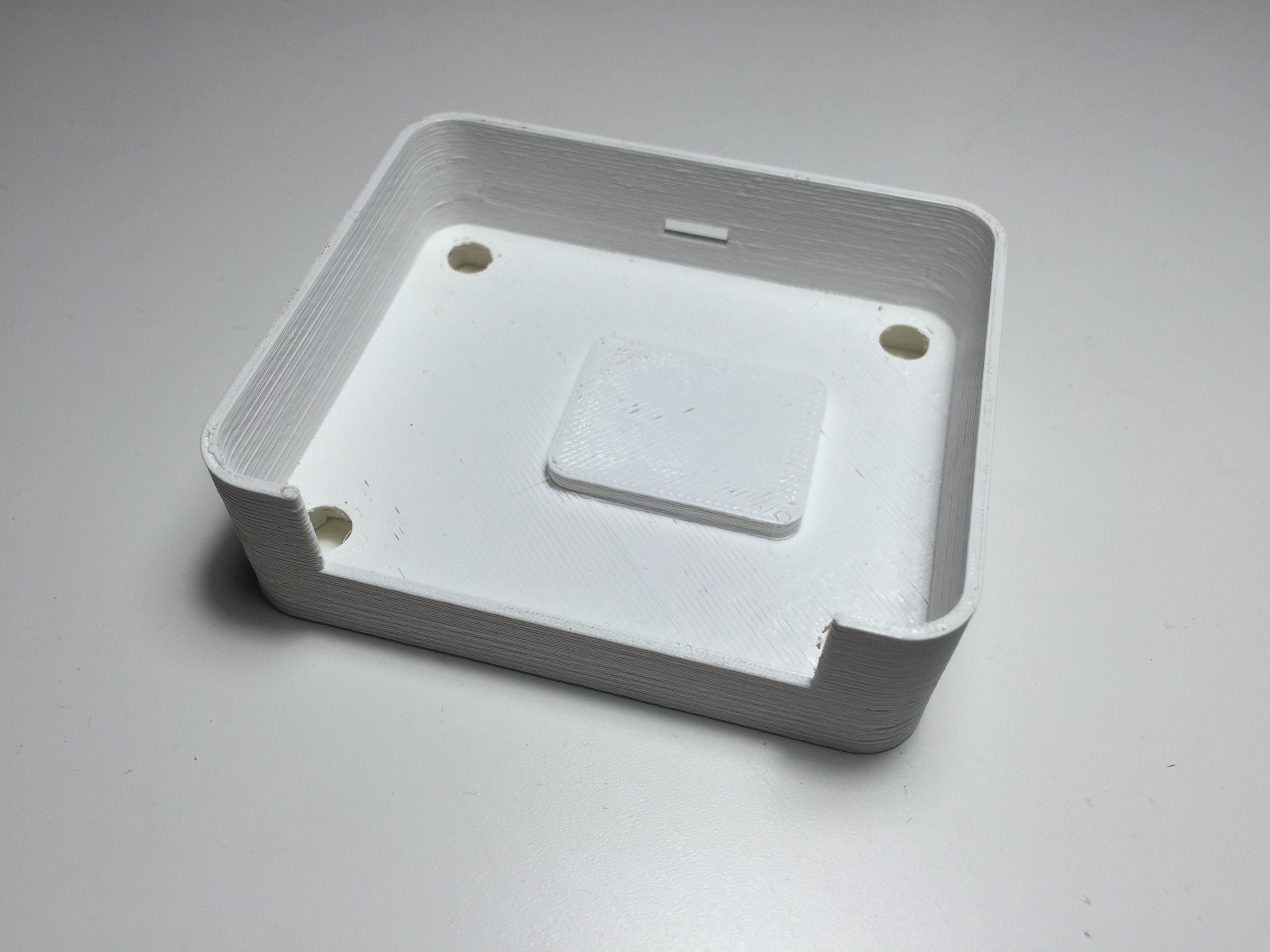
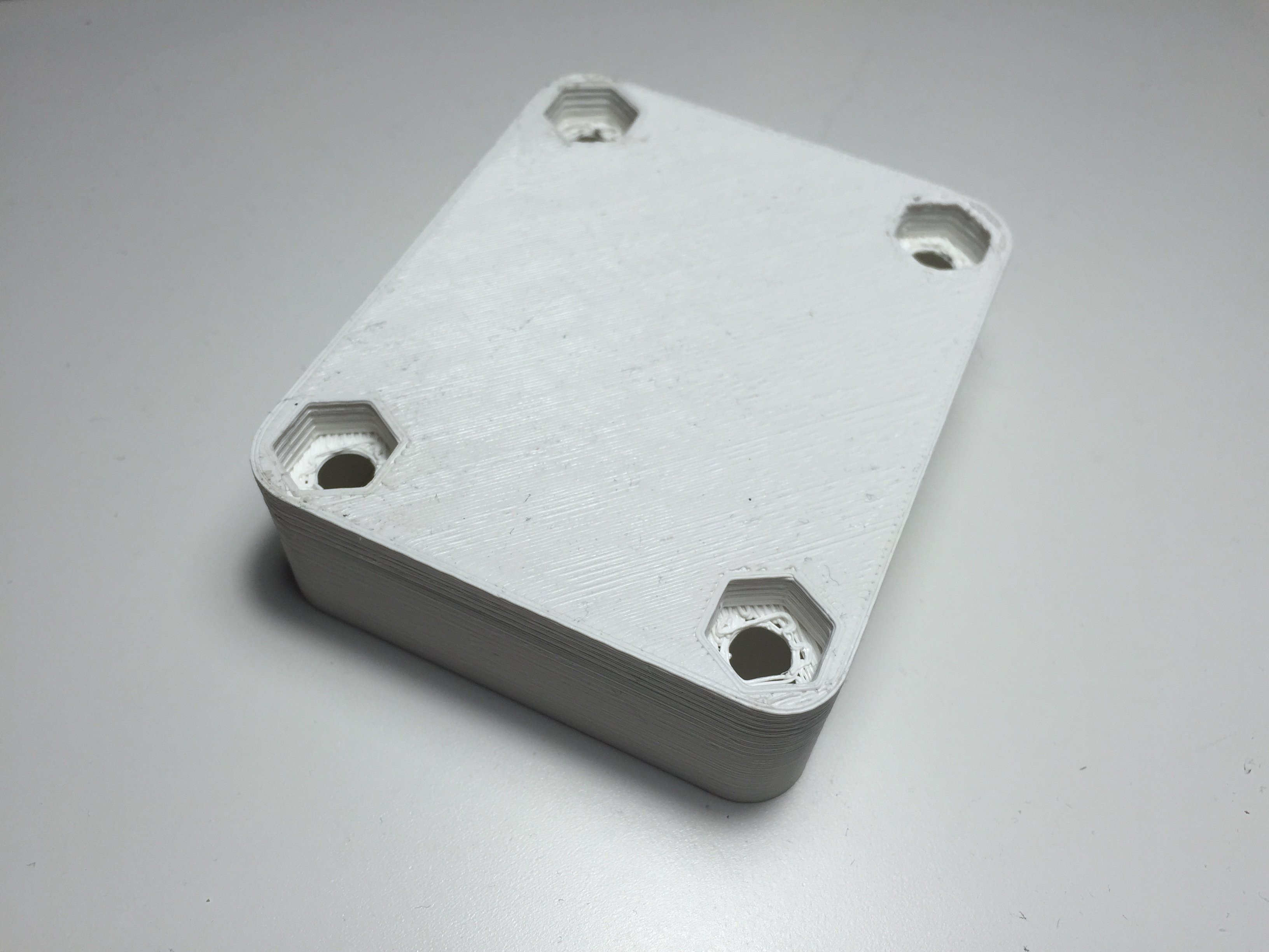
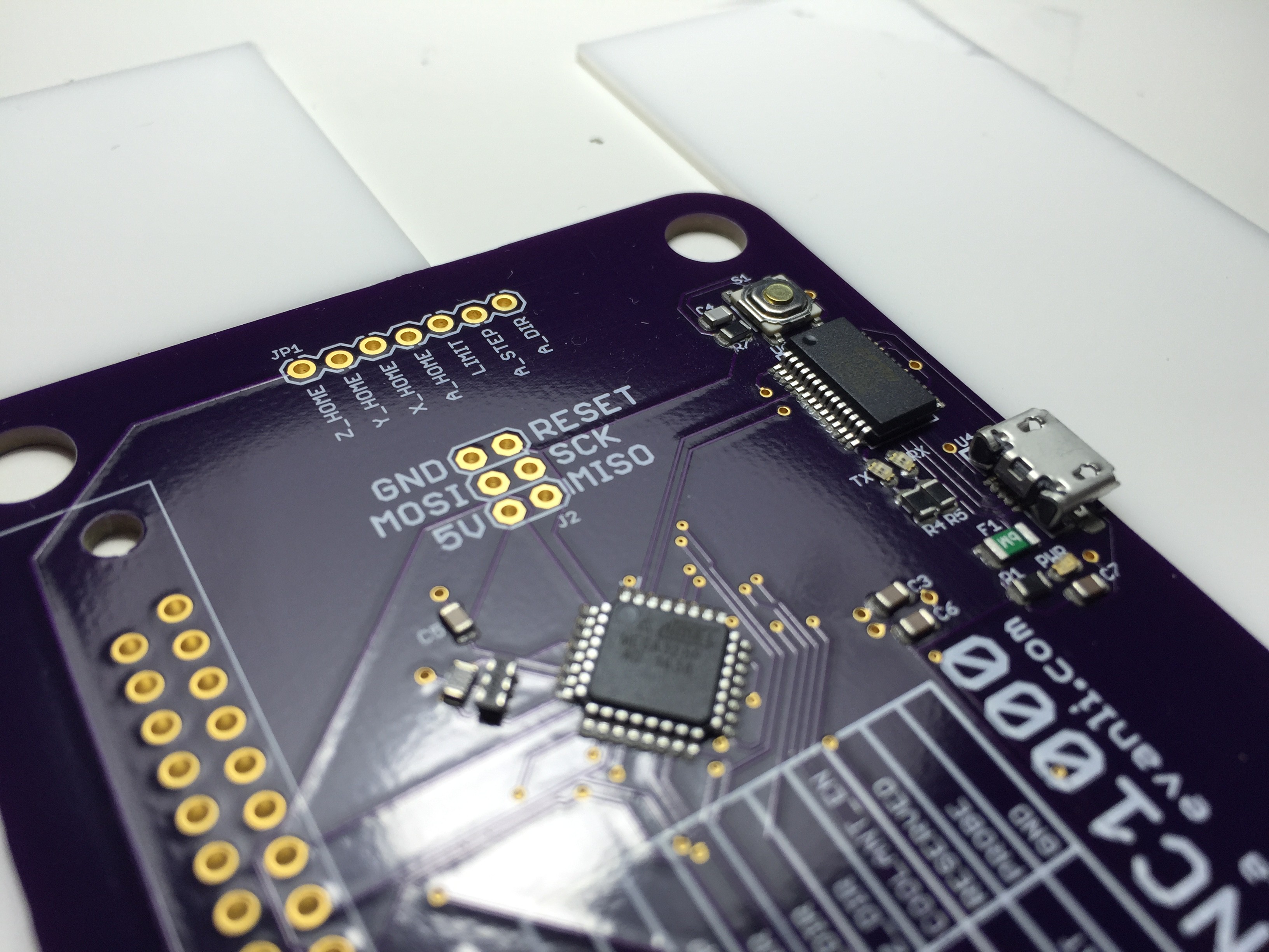
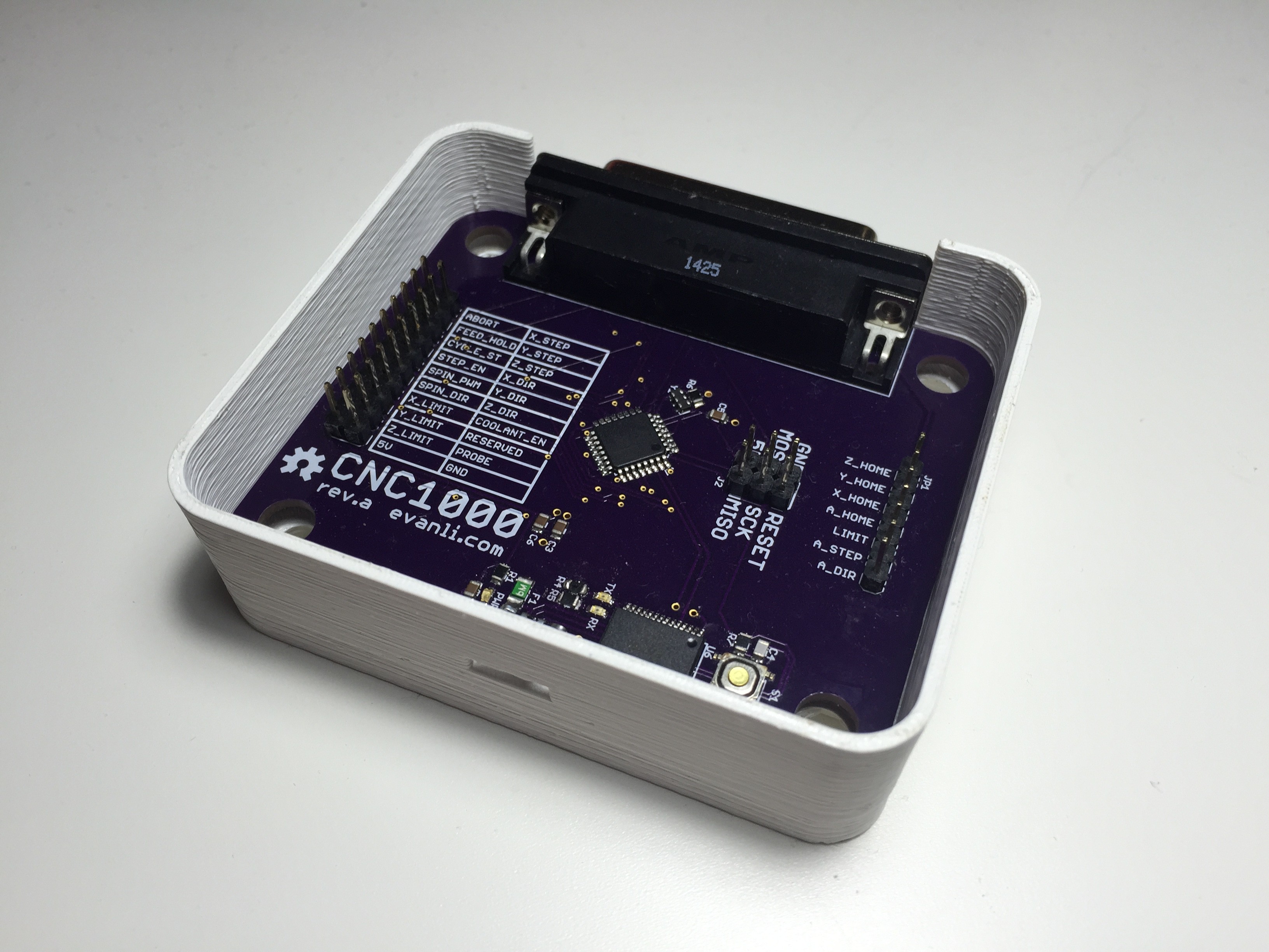 The model has tolerances for my 3D printer incorporated into it, so it fits like a glove.
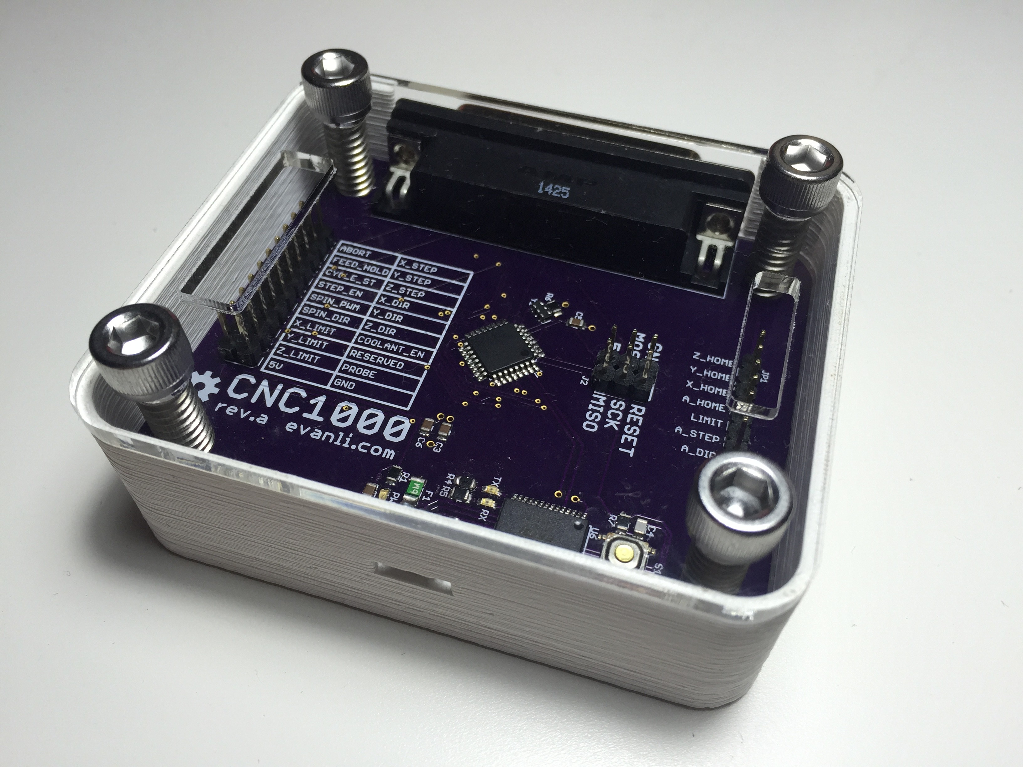
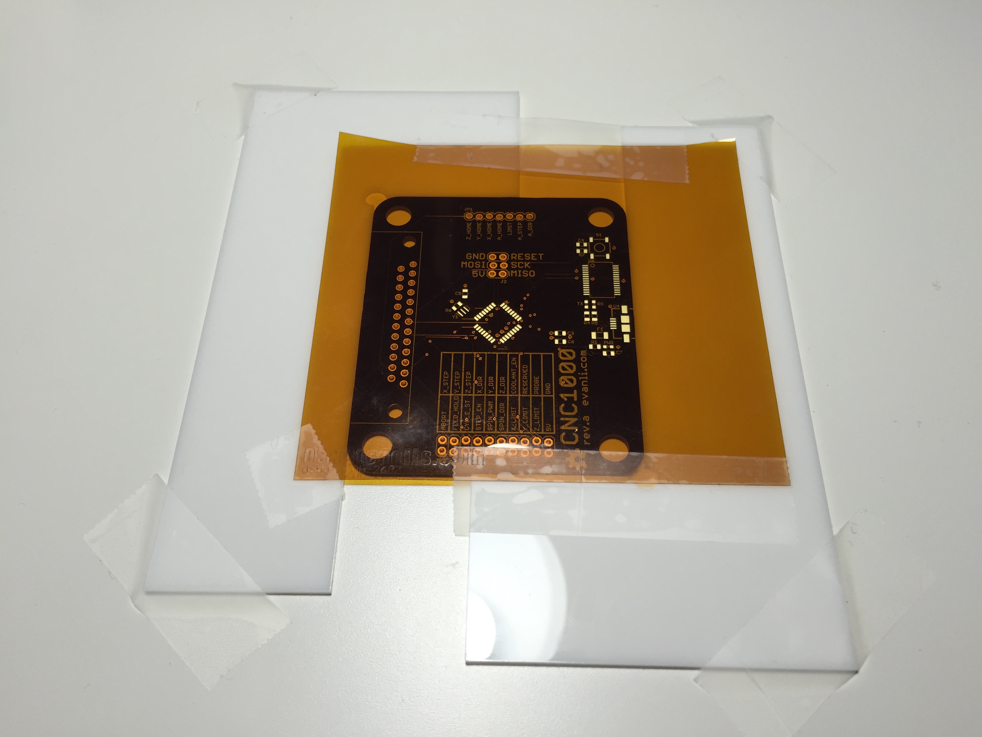 Putting on solder paste is always a delicate task. Basically I just taped the PCB in place with some acrylic L shapes. The stencil is aligned and secured in place with more tape.
 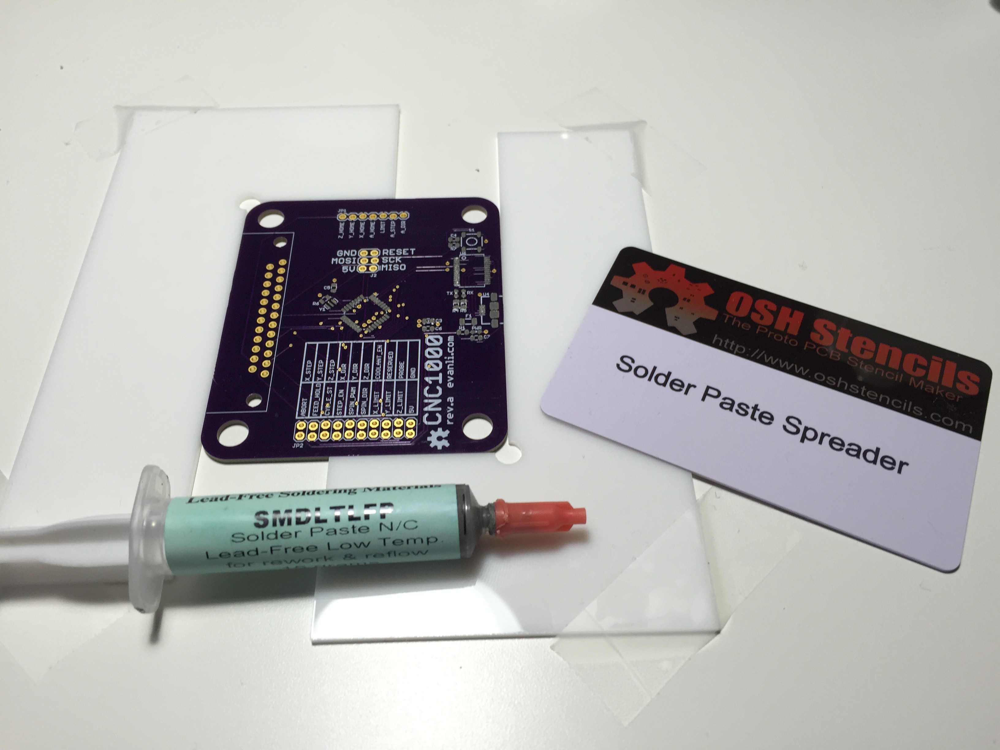 Dump some solder paste on and spread it with a convenient card from OSH Stencil.
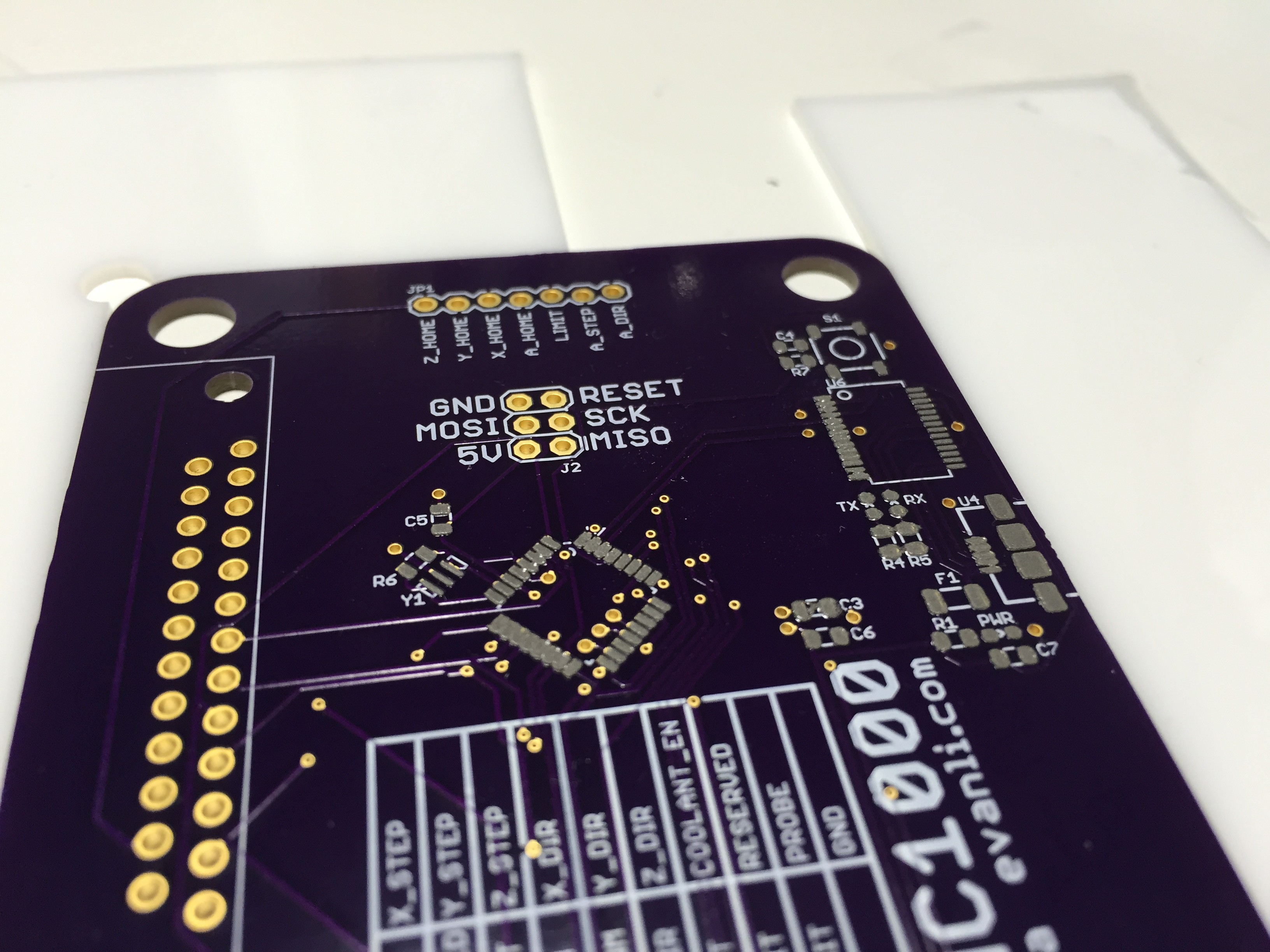


 Timo Birnschein
 dar.ryl
 Thomas Bladykas
 J.C. Nelson