Close
0%
0%

Borg Washing Machine

Homemade PLC-like electronic replacement for the mechanical timer in my washing machine.

Similar projects worth following
A replacement for a washing machine's mechanical timer. The original controller started to fail (erratic behavior), and the OEM replacement was ridiculously expensive. Since I've always wanted to make my own PLC, this was the perfect excuse to do so.

I recently acquired a second hand washing machine, and while all the mechanical bits (motor, tub and all rubber parts) were in good shape, the electrical system was not. Some switches were broken and the control timer started failing, causing interrupted cycles that ultimately resulted in damp soapy clothes.

Inspired by a similar project by a fellow Argentinian tinkerer, I decided to replace the whole electrical system outright with my own. My plan was to build something more heavy-duty, backed by my previous job experience working with industrial electronics, interfacing circuits, safety, and ladder logic. This has been a great opportunity to put all that experience together into a personal project.

The guiding principles for this design are:

  • Robustness: fail-safe hardware and software.
  • Flexibility: to be able to add more features down the line.
  • Low cost: use repurposed components and simple designs to keep the build, maintenance and repair costs down for the lifetime of the machine.

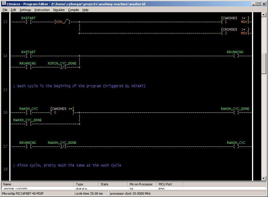
Since I have an abundance of Microchip PIC16F887s lying around, it was an easy choice for the main processor as it offers more than enough power for this application, and I have spares. The firmware design was a harder decision, however. At first I wanted to code a ladder logic interpreter from scratch (and still do), but I ultimately settled on LDMicro to get a prototype done faster since it supported my processor and my clothes wouldn't wash themselves.

I'll continue describing the nitty-gritty details of this project with a series of build logs, so stay tuned.

  • 1 × PIC16F887 Cheap 40 pin microcontroller
  • 1 × Perfboard For those cases where joining dozens of pins by hand is easier than making a PCB
  • 1 × Hacked USB car charger Easiest way to get efficient, clean 5V from the main 24V supply

  • Firmware

    Jose Ignacio Romero02/16/2015 at 23:22 0 comments

    [January 15, 2015]

    For the initial test runs of the machine I wrote a minimal program in ladder logic for a full, fixed wash, rinse, and spin cycle. I chose LDmicro as the runtime since it's very simple to use and supported my processor pretty well.

    The "heart" of the program is a sequences of cycles: wash, rinse and spin. The wash and rinse cycles are divided into 3 phases each: fill, tumble and drain. As each phase is completed, a coil is sealed and the next phase starts. once all phases are completed, the coils are released and a counter is decremented, restarting the cycle. Once the counter reaches zero, a coil is sealed and the next cycle is started. The spin cycle uses a simple timer as end condition. Once all cycles are completed successfully, the "program running" coil is unlatched and the program halts, unlocking the washer's door.

    There are several safeties built in that would pause the program if triggered (for example, door not locked, overflow switch.) One thing that is missing however is an alarms system to report the errors to the operator, and abort sequences like draining with the pump on overflow for example.

    Next version of the program will have an operator control panel to select among several predefined cycles and edit their parameters. Another thing to add is a product dispensing system to add detergent and fabric softener as needed in different parts of the cycle.

    LDmicro source and text conversion available on gist

  • Logic board

    Jose Ignacio Romero02/08/2015 at 18:07 0 comments

    [January 1, 2015]

    The brains of this washing machine are built around a PIC16F887 microcontroller with a 20MHz crystal. Since I'll probably be modifying this board often I didn't bother designing a PCB and used perfboard instead.

    Power comes from the main 24VDC rail and goes through a USB car charger's circuit board, which steps it down to a clean 5 volts to power the µC. The 24V power also feeds the pull-up resistors of the input interface:

    This circuit is repeated for each of the 8 inputs, it's basically a voltage divider to bring 24v signals down to 0-5V for the PIC's input ports. The 9v1 Zener diode rejects all noise under 9V, preventing false transitions in the output. I copied this design from a 1980's vintage Italian PLC I worked a lot with in a previous job. The circuit proved fairly reliable for the last 30 years under far less than ideal conditions, so I thought it was worth using for this application. I feel the Zener was really important in that particular circuit because it used TTL technology, which has a much lower noise margin around 0v than CMOS. Still, I think it does help when there's a lot of electrical noise around.

    The outputs are just wired to a ULN2003 array of 7 NPN transistors, which drive the relays in the power boards.

    I wired an ICSP header for ease of reprogramming, and the µC still has many free IO pins, including the UART, which I have reserved for future features (Maybe "Internet of Things", remote control panel, etc.)

  • Relay board

    Jose Ignacio Romero02/07/2015 at 23:01 0 comments

    [December 28, 2014]

    I designed and built the "power" board of the machine first because I felt that was the most challenging thing to get right. I took great care to respect the current ratings of every element and clearance/creepage distances since this board would interface my 24V logic with 220V mains stuff.

    An unpleasant surprise I found while disassembling the machine is that two signals I thought would be dry contacts actually are single ended 220v mains signals coming from the control element. Namely, the door locker and the thermostat "ready" signal. Since those two signals are very important and there's no easy way to wire them with 24VDC I designed an optocoupled interface circuit that would take the 220V signal and activate a standard NPN output for my 24V PLC input stage.

    I don't claim this design to be super innovative, but I did combine several ideas I saw in other industrial circuits. The 220VAC signal enters P1 and has to go through R1 and C1 to get to the bridge rectifier formed by D1, D2, D3, and D4, which in turn feeds D5 (LED) and IC1 (optocoupler).

    R1 and C1 have an impedance of ~16kΩ for 220VAC@50Hz, which would limit the RMS current through the LEDs to around 13mA, VR1 is actually a 10V TVS diode in the final board. It's function is to absorb high frequency spikes that would go right through C1 and cause big current spikes since a capacitor's impedance falls with frequency. In theory the 10V clamp would limit the worst case current spike through the LEDs to less than 30mA, which is fairly safe.

    Due to the bridge rectifier action, the LED and optocoupler will stay on for most of the signal's cycle, except for brief instants around the zero crossing point of the signal where the voltage drops below ~6 volts. Those short drops would show up as low duty cycle 100Hz pulses in the output. To get rid of those I needed a low pass filter. At first I thought about adding a couple transistor stages with the filter in the middle, but then I realized I could hack a low pass filter with the opto itself. I did that by adding base capacitance to the output transistor. I simulated the circuit with LTspice and tuned the R and C values to give a decent response. The circuit worked as designed first go.

    The relay part is fairly unremarkable, it has a standard RC snubber and MOV to protect the contacts. The only hack-y part is the way I connected the LED to save parts and power. Since the relay has a DC resistance of around 4kΩ, connecting it in series provided enough current to brightly light it. Connecting the LED with a 4k7 resistor in parallel with the coil would have burned as much power in the ballast resistor as the relay itself!

    Note: The optocoupler circuit should work unmodified for 120VAC@60Hz, since the C1+R1 impedance would then be ~13k5 which would limit the current to ~8.5mA, it's best to optimize the components for the line voltage in question, though. Oh, and I didn't just use a 15k resistor there because that would dissipate 3W, which I felt would be too wasteful, and an annoying amount of heat to get rid of!

View all 3 project logs

Enjoy this project?

Share

Discussions

fayez-56 wrote 01/13/2018 at 04:26 point

greating job

  Are you sure? yes | no

Similar Projects

Does this project spark your interest?

Become a member to follow this project and never miss any updates