Joe De Filippis
Here is a continuation of the description:
The first problem was that the original readout had multiple markings for the different ranges. I couldn't see any easy way around this with the microcontroller so I programmed it to display all four ranges at any time. That meant I had to be aware of what range I was on, which is the way it started out, so no convenience gained or lost here.
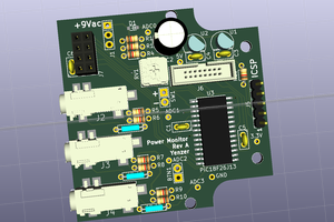
The next problem was the actual wires I read with the ADC to calculate from. I thought one would have been ground and the other would be the only one I needed, but that wasn;t true for some reason. Not wanting to waste too much time on it, I swapped to an MSP430 chip with an SD16 input, so I could take the potential difference across both wires, regardless of what the lower potential was.
Another problem that kind of blind-sided me was the AC adapter's transient voltage when the power was switched on. Because I wired the adapter to only get power when the supply was turned on it would ramp up to its final voltage over a second or two. The MSP430 would always get enough voltage to start up before the LCD did, which that caused communication issues. It was fixed by adding a couple second delay to the code, but was extremely annoying because when I was in the testing phase this wasn't an issue.
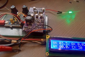
While testing it I had the raw ADC values printed out to the LCD, which I plotted vs values from a multimeter. Using this information, I got an equation for the slope of the line of best fit, and programmed it into the microcontroller.
That's pretty much it. It's not the prettiest project, but it works and was a good learning experience for me.
 Sebastian
 ivorivetta