 Andrew Sowa
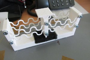
A TSL257T light sensor is used in conjunction with an oscilloscope to capture 120hz flicker in real-time. The sensor consists of a light to voltage converter with a built in op-amp for signal amplification. The device is powered from a 5VDC source and outputs an analog signal from ~0-5VDC. Zero voltage represents no light and 5V an arbitrarily high value. Because the sensor has a fixed amplification, it is easily saturated with low light levels. This makes it useless for measuring an emitting with any significant light output. A automatic linear shutter of sorts was used to restrict the light to the sensor so the peak output stayed around 4.5V. I designed a simple triangle based slider in Sketchup to test my theory. I was able to 3D print it and verify it was good enough. After struggling to add a servo mount in Sketchup, I used this as an opportunity to learn Fusion360. It made it easier to make changes as I went and eventually produced a successful design. I ended up with a simple dual horn linear motion. To quickly get it working, I wrote a simple Arduino sketch to do a peak detect and adjust the servo accordingly.
0%
0%
Flicker Measurement Sensor w/ Auto Shutter
The goal of this project is to accurately measure and characterize the 120hz flicker from a variety of light sources.
Become a Hackaday.io member
Already have an account? Log in.
Just one more thing
To make the experience fit your profile, pick a username and tell us what interests you.
Pick an awesome username
hackaday.io/
Your profile's URL: hackaday.io/username. Max 25 alphanumeric characters.
Pick a few interests
Projects that share your interests
People that share your interests
 jaromir.sukuba

 Est
Est
 Hulk
Hulk