Close
0%
0%

ARDUINO MPPT SOLAR CHARGE CONTROLLER

An Arduino based Solar MPPT charge controller.

Similar projects worth following
In India most of the people are living in rural areas,400 million people that are currently have no access to electricity.Despite India being the world's 5th largest energy producer,the existing electric grids are not capable of supplying the electricity need to those poor people.
So the need for clean, affordable alternatives is obvious.Solar power have the advantage of being less maintenance and pollution free.
To provide basic need of electricity and improve the socio-economic positions of rural people, I started this project from basic lighting system and a simple PWM solar charge Controller in March-2014.The feedback was incredible on Instructables. After working over one year to improve the controller, I have landed up in this stage.This project is on MPPT solar charge controller which can charge a commonly used 12V lead acid battery from a solar panel.This is more sophisticated,30 to 40 % more efficient and have several advantages over the other charge controllers.


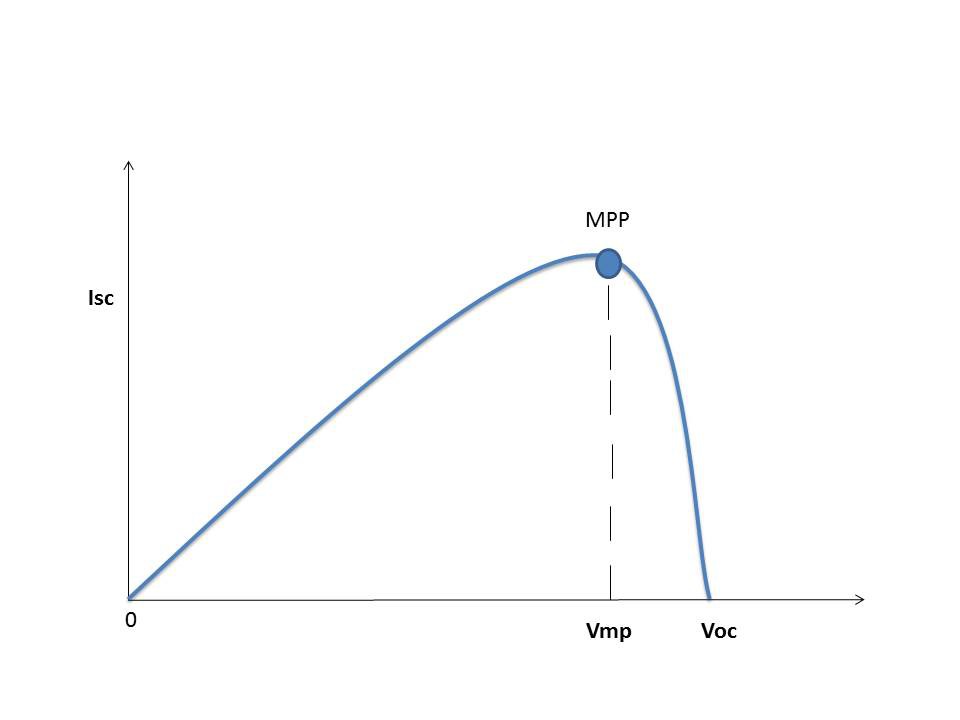
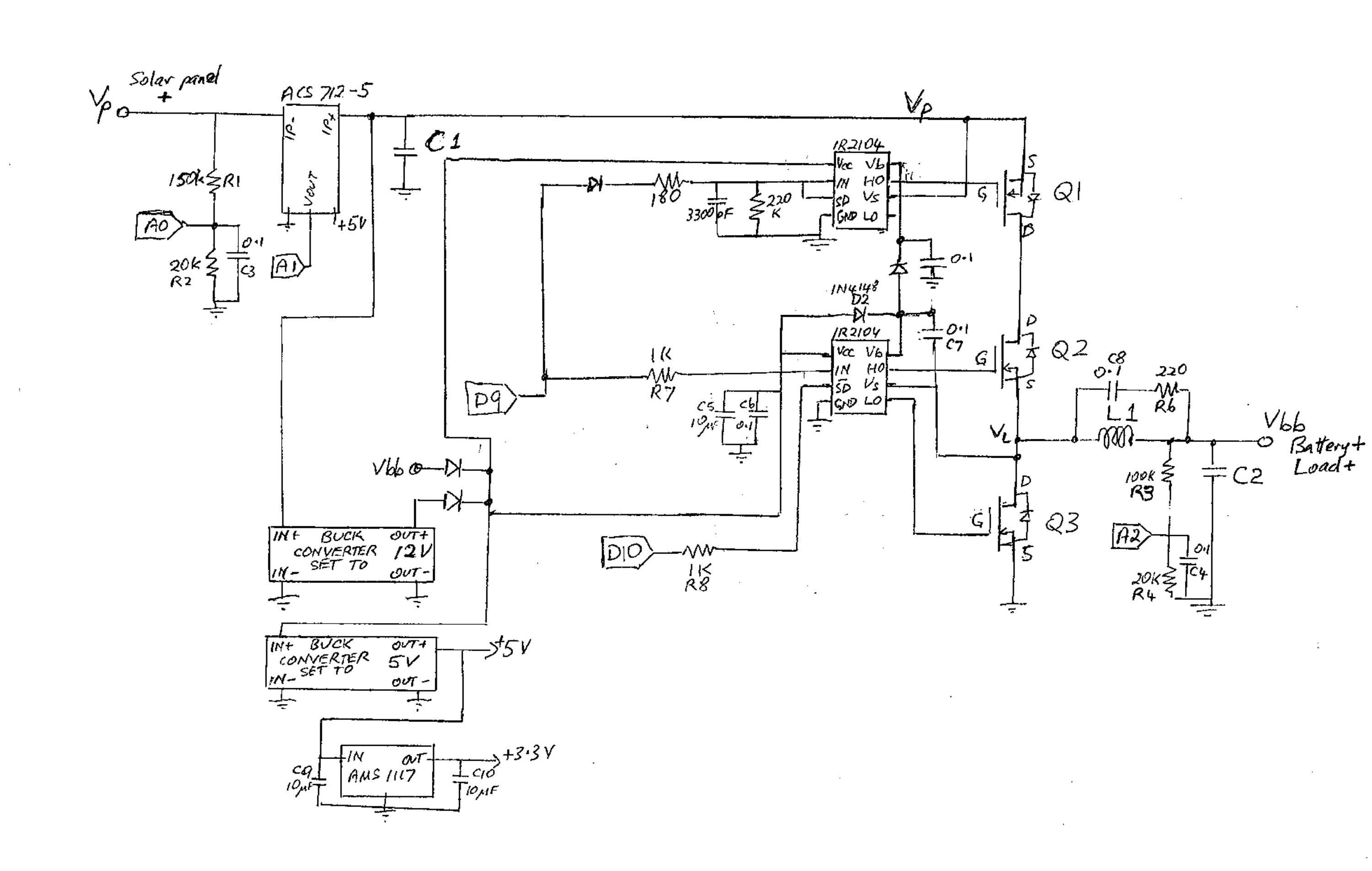
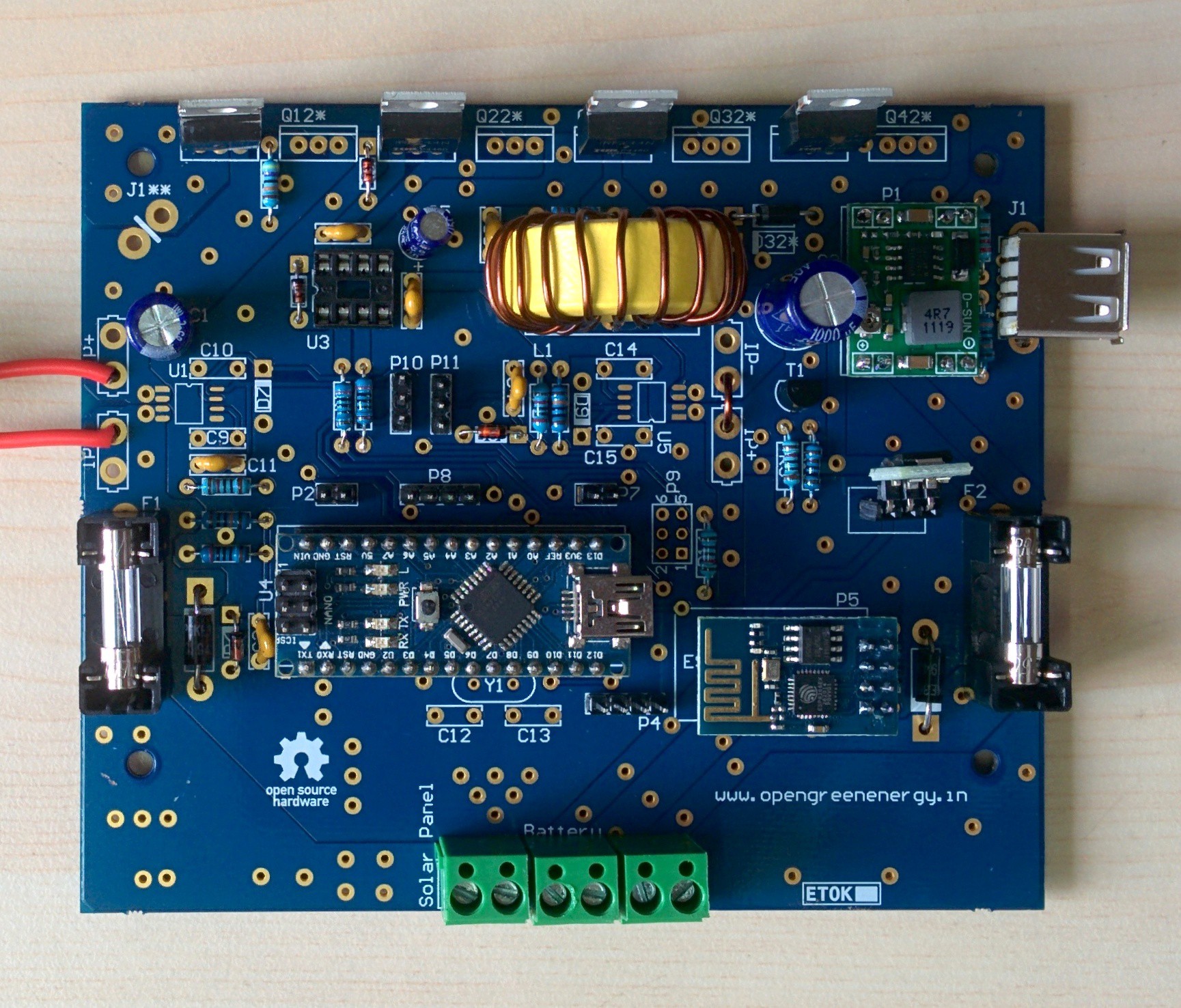
MPPT stands for Maximum Power Point Tracking. MPPT charge controllers used for extracting maximum available power from PV module under certain conditions.The Maximum Power Point Tracker (MPPT) circuit is based around a synchronous buck converter circuit.It steps the higher solar panel voltage down to the charging voltage of the battery. The Arduino tries to maximize the watts input from the solar panel by controlling the duty cycle to keep the solar panel operating at its Maximum Power Point.

You can find more details on MPPT here

Algorithm :


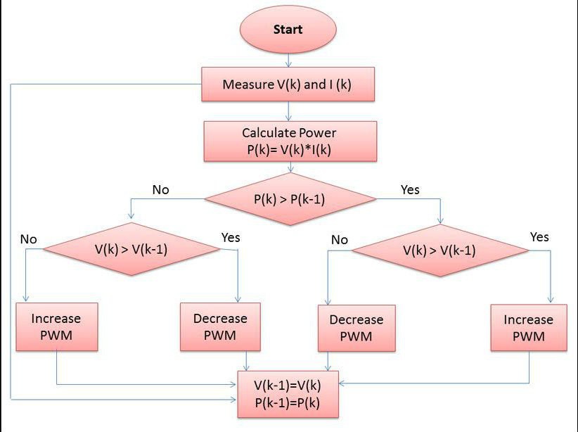
The Maximum Power Tracker uses an iterative approach to finding this constantly changing MPP. This iterative method is called Perterb and Observe or hill climbing algorithm.To achieve MPPT, the controller adjusts the voltage by a small amount from the solar panel and measures power, if the power increases, further adjustments in the direction are tried until power no longer increases.

The voltage to the solar panel is increased initially, if the output power increase, the voltage is continually increased until the output power starts decreasing. Once the output power starts decreasing, the voltage to the solar panel decreased until maximum power is reached. This process is continued until the MPPT is attained. This result is an oscillation of the output power around the MPP.

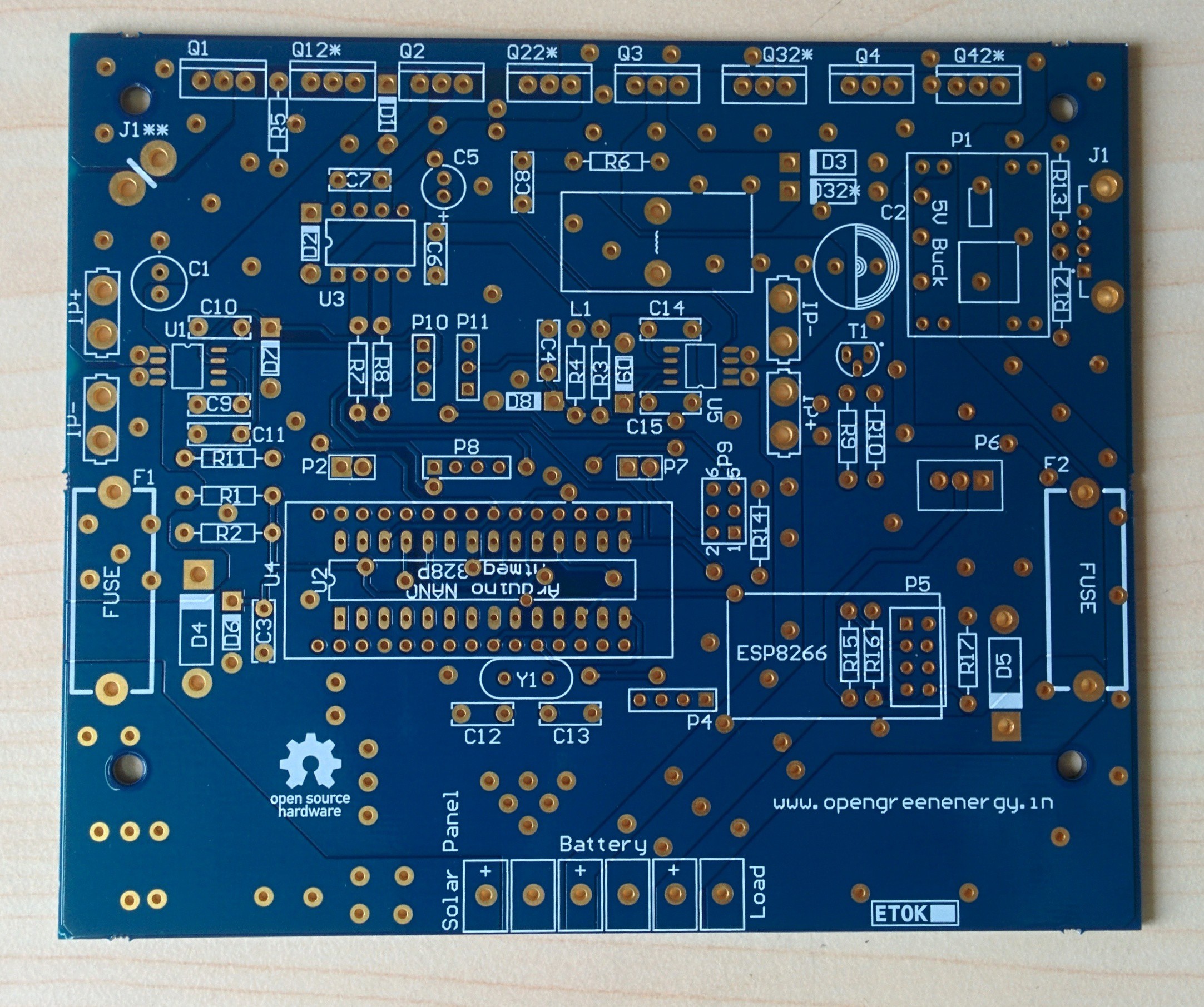
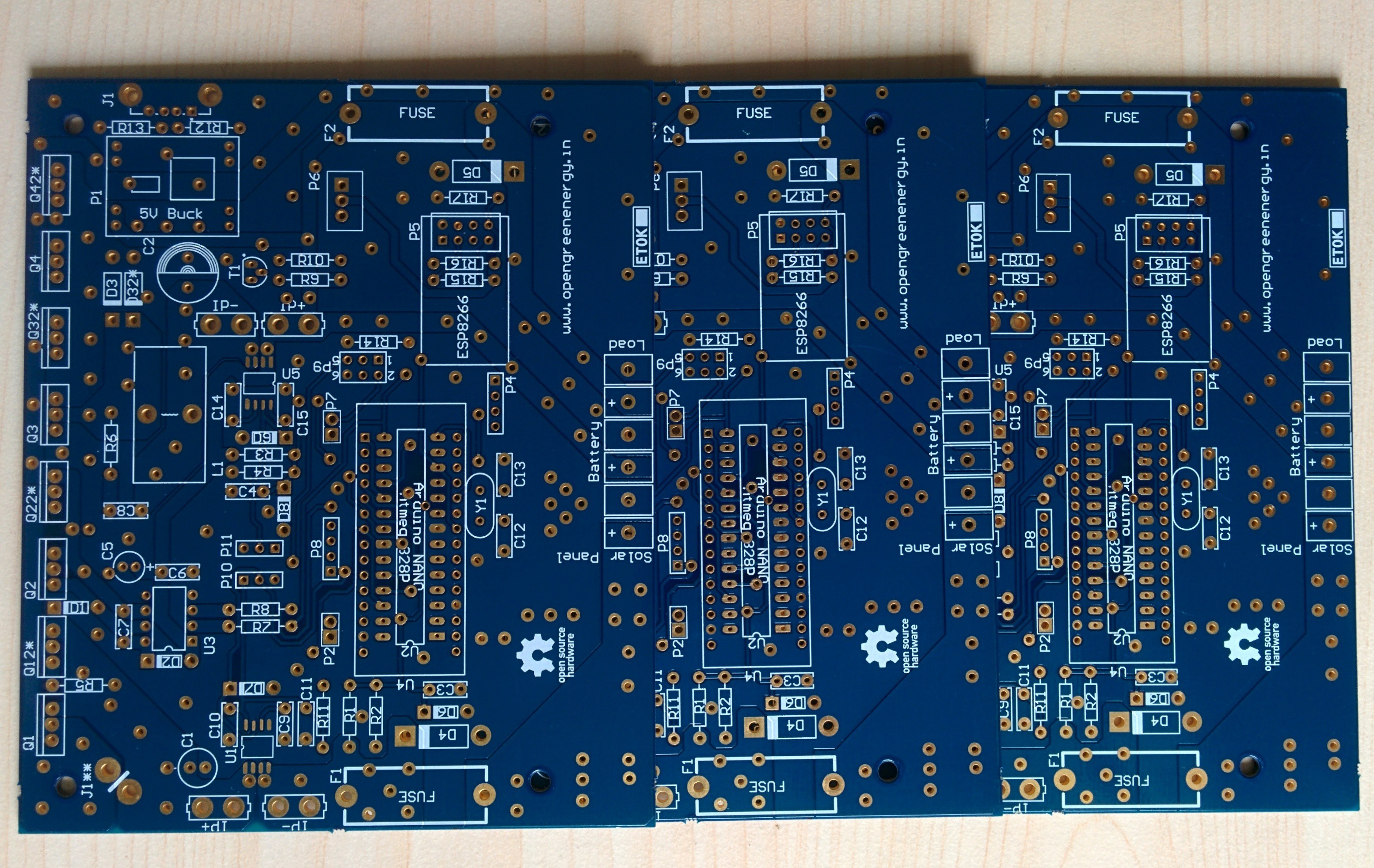
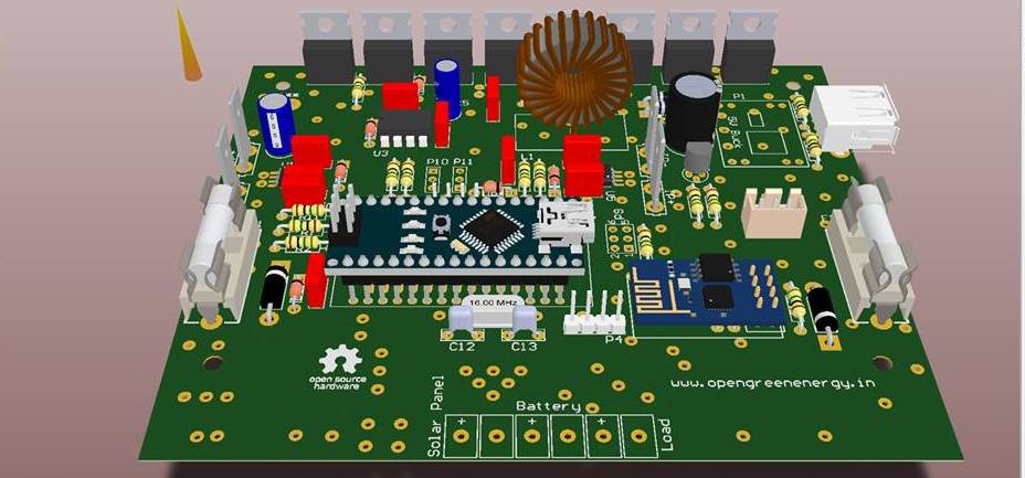
Specification of version-3 charge controller :

1.Based on MPPT algorithm

2. LED indication for the state of charge

3. 20x4 character LCD display for displaying voltages,current,power etc

4. Overvoltage / Lightning protection

5. Reverse power flow protection

6. Short Circuit and Over load protection

7. Wi Fi data logging

8.USB port for Charging Smart Phone /Gadgets

Electrical specifications :

1.Rated Voltage= 12V

2.Maximum current = 5A

3.Maximum load current =10A

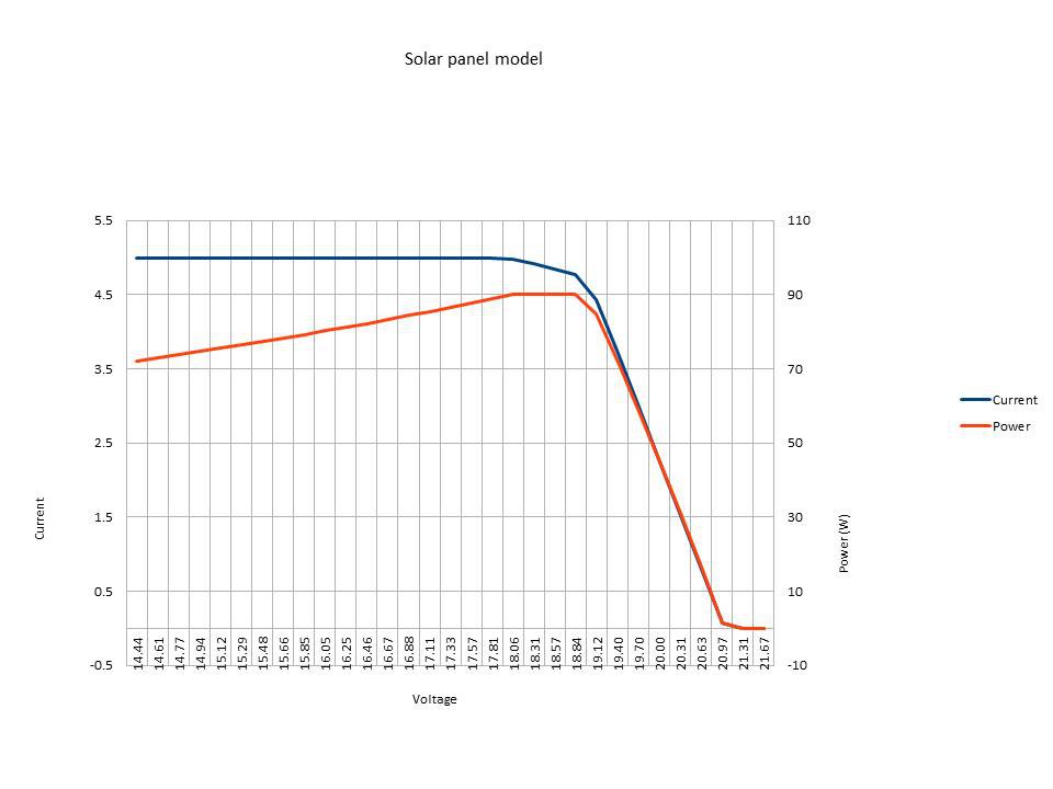
4. In put Voltage = Solar panel with Open circuit voltage from 12 to 25V

5.Solar panel power = 50W

  • 1 × Arduino Nano Atmega328P based Microcontroller
  • 3 × Current Sensor ACS712 hall effect Current Sensor
  • 2 × LM2596 module DC-DC Buck Converter module
  • 1 × ESP8266 WiFi SOP module
  • 1 × 20x4 char LCD display Yellow Serial 2C/TWI 2004 20X4 Character LCD Module Display

View all 49 components

  • Battery Temperature and Charging Voltage Compensation

    Open Green Energy09/16/2015 at 09:45 0 comments

    All chemical reactions are affected by temperature. Battery charging is also an electrochemical reaction, so it too is affected by temperature. As the battery gets warmer, the gassing increases. As the battery gets colder,it becomes more resistant to charging. So battery charging voltages should be corrected based on battery temperature. This adjustment is referred to as temperature compensation, a charging feature that helps ensure that a battery is neither undercharged nor overcharged regardless of battery temperature.

    Using normal target voltages to charge a battery that is colder than approximately 25ºC (77ºF) will result in an undercharged battery, which will deliver lower performance, reduced life and a higher life cycle cost. Applying normal target voltages to a battery that is hotter than 25ºC may result in an overcharged battery. This condition could lead to the drying out of VRLA battery cells. With flooded cells, the result will be excessive outgassing, increased battery maintenance in the form of more frequent watering and reduced battery life due to thermal stress. In fact, some battery manufacturers and charger manufacturers recommend not charging a battery that is 50ºC (122ºF) or hotter.

    Temperature Sensor :

    To monitor the battery temperature a DS18B20 1-Wire digital temperature sensor from Maxim IC will be used. It can measures temperatures from -55°C to +125°C. Fahrenheit equivalent is -67°F to +257°F with ±0.5°C accuracy.

    We choose a waterproofed version of the DS18B20 Temperature sensor. It is quite handy to measure something far away, or in wet conditions.

    You can see it here

    You can see the Data Sheet

    Temperature Compensation Formula:

    minus 0.018 volts per degree Celsius

    Example :

    1. Let the battery temperature is 0 degC and float voltage is 13.8V ( STC : at 25degC )

    Compensation Required = ( 0 - 25) * ( - 0.018 ) = + 0.45V

    Compensated Float Voltage = 13.8 + 0.45 = 14.25 V

    2. Let the battery temperature is 35 degC and float voltage is 13.8V ( STC : at 25degC )

    Compensation Required = ( 35 - 25) * ( - 0.018 ) = - 0.18V

    Compensated Float Voltage = 13.8 - 0.18= 13.62 V

    So cold batteries ( example-1) require a higher charge voltage in order to push current into the battery plates and electrolyte, and warmer batteries( example-2 ) require a lower charge voltage to eliminate potential damage to valve regulated lead acid (VRLA) cells and reduce unnecessary gassing if flooded cells are used.

    Reference : http://solarprofessional.com

  • Software requirements for MPPT controller V3.1

    Open Green Energy08/30/2015 at 15:06 2 comments

    Software requirements for MPPT controller V3.1

    Draft by Keith Hungerford, updated 12th September 2015

    Charging states

    The charger operates in one of several charging states, depending on the sunlight level.

    Charger OFF state

    At nil or low sunlight levels, as indicated by solar voltage below battery voltage + 0.5 Volts, the charger state is OFF.

    Transition from the OFF state occurs when

    a) if battery voltage is greater than 11.5 volts and solar voltage rises above battery voltage + 0.5 Volts

    b) if battery voltage is less than 11.5 volts and solar voltage rises above 12.5 volts.

    When either of these voltage conditions is met the charger goes into one of the following states:

    i) Float state if the battery voltage is greater than the Float voltage;

    ii) Boost state if the battery voltage is less than the Float voltage and the Boost time since the last night time is less than [1 hour];

    iii) Bulk state if the battery voltage is less than the Float voltage and the Boost time since the last night time is greater than [1 hour]

    In all 3 cases initially the controller will use the DCM charging algorithm.

    Boost DCM and Bulk DCM states

    When in the Boost DCM or Bulk DCM state, the charger can go to OFF state if the solar voltage falls below (battery voltage + 0.5 Volts).

    The charger can go to Boost CCM or Bulk CCM state if the Solar Power rises above 10% of the rated power.

    The charger can go to the Float state if Battery voltage rises above Float.

    The charger can go from Boost DCM to Bulk DCM if the Boost time since the last night is greater than Boost duration.

    Boost CCM and Bulk CCM states

    When in the Boost CCM or Bulk CCM state the charger can go to Boost DCM or Bulk DCM if the Solar Power falls below 10% of rated power.

    • The charger can go from Boost CCM to Bulk CCM if the Boost time since the last night is greater than Boost duration


    Float state

    The float state is functionally the same as Bulk state when the battery voltage reaches Float.

    When in Float state the charger keeps just sufficient current flowing to the battery to maintain the battery voltage at Float.

    Charging algorithms


    CCM algorithm

    Continuous Current Mode (CCM) applies when the available solar power is more than 10% of the rated power (strictly, when the current in the inductor always flows towards the battery, but this is difficult to measure directly in the software so we use the power level as a proxy estimate).

    In this mode, the PWM period is set at 12 microseconds. The PWM duty cycle is set either at a value that achieves maximum power, or to meet the charging voltage required by the battery (see battery management conditions below). When it is required to reduce the charging rate so as to limit the battery voltage, the PWM duty is reduced, thereby increasing the panel voltage above the maximum power point and reducing the current accordingly.

    The Fast PWM mode of the Arduino is used to generate this PWM. The PWM period of 12 microseconds is 192 clock cycles at 16 MHz. The PWM period is divided into a Panel Connect phase followed by an Earth Connect phase. The length of the Panel Connect phase is controlled by PWM Duty.

    When maximising power, the power level is measured approximately every 0.5 milliseconds and is compared to the previous power level measurement. The PWM duty cycle is changed up or down by 1 CPU clock cycle after every measurement. After the first measurement, the PWM duty cycle is increased. On subsequent measurements, if the power level is increased or is the same as the previous measurement, the PWM duty cycle is changed in the same direction as in the previous cycle. If the power level is decreased from the previous cycle, the PWM duty cycle is changed to go in the opposite direction to that in the previous cycle.

    When tracking the allowable battery voltage, the battery voltage is measured approximately every 0.5 milliseconds and is compared to the target value. If the new value is within +0.1 volts of the target value, the PWM duty is left unchanged. If the new value is...

    Read more »

  • Overview of Version-3.1

    Open Green Energy08/30/2015 at 14:50 7 comments

    After lot testing we observed that MOSFET ( Q3 ) in ver-3.0 design is burning repeatedly.We tried to modify the existing software but not find any satisfactory result.

    The other problem was that MOSFET Q1 ( in V-3.0) conduct even when there is no solar input.

    To solve the above problems and enhance the power handling capability we are modifying both the hardware and software.This is named as Version-3.1 Charge Controller.This version have 3 options.

    1. 5 Amp version :

    T94-26 toroid, 48 turns of AWG20 wire to give 135 uH (it takes almost 1.5m of wire)

    Q1, Q2 and Q3 all pairs of IRFZ44N MOSFETs (6 in all).

    C1 will be 3 * 220 uF low ESR capacitors in parallel,

    C2 will be a single 220 uF low ESR capacitor

    Single ACS712 on the panel side as per version 3.0

    2. 8 Amp version :

    T106-26 toroid wound with 23 turns of a compound wire made from 3 strands of AWG20 wire twisted together to give 47 uH (this takes about 3.1 m of wire).

    Q2 will be a pair of FDP150N10A MOSFETs in parallel.

    C1 will be 5 * 220 uF low ESR capacitors in parallel,
    C2 will be a single 220 uF low ESR capacitor

    Two ACS712, one on the panel side as per version 3.0 and one in series with the battery.

    3 10 Amp version :

    T130-26 toroid wound with 23 turns of a compound wire made from 4 strands of AWG18 wire twisted together to give 41 uH (this takes about 4.5 m of wire).

    Q2 will be a pair of FDP150N10A MOSFETs in parallel.
    C1 will be 6 * 220 uF low ESR capacitors in parallel,
    C2 will be 2 * 220 uF low ESR capacitors in parallel.

    Three ACS712, one on the panel side as per version 3.0, one in series with the battery and one in series with the load.

    Here is a rough sketch for V-3.1

    You can download the complete schematic from here

    We are working on new PCB for V-3.1 Here is the sample of one

    The drive circuitry (common to all 3 versions) will use 3 separate IR2104 driver chips, one for each of Q1, Q2 and Q3. We drive the Q1 and Q2 drivers from pin D9 and HO1 and HO2, and drive Q3 from pin D10 and LO3.

    In driver chips 1 and 2, pins IN and SD are driven in parallel by Arduino output pin D9. In the case of driver 1 (for Q1) there is a low pass RC filter in series, with a time constant of about 1 ms. Driver 2 is driven directly (as in the current circuit, but probably with a slightly higher series resistor to allow more current for the Q1 driver and its RC filter).

    In driver chip 3, IN is driven by D9 and SD is driven by D10.

    The purpose of using separate drivers for Q2 and Q3 is to enable us to switch Q3 OFF to operate in Asynchronous mode at low current levels when the controller will be in DCM (Discontinuous Current Mode). There may be a better way to do this but in the short time we have available this is a simple option and easy and reliable to implement.

    All 3 versions should have LCD displays, WiFi, LED indicators (maybe with a more fancy coding scheme to separately indicate DCM and CCM).

    All 3 versions should be able to cope with either 18 V or 30 V panels, and use algorithms that stop them burning out if the panel can produce more current than the rating allows. This can all be done auto-detect.

    All the components exposed to panel voltage need to be rated for at least 40 V (in particular C1 and our buck converter to generate 12V for the drivers and to power the control electronics.

  • Overview of MPPT algorithm modelling

    Open Green Energy08/26/2015 at 07:29 0 comments

    Panel model consists of a simple step-wise linear model of a solar panel.See the above figure.

    1. Constant Current : up to 18 volts

    2. Constant Power : between 18 and 19 volts

    3. Power decline linearly to zero : between 19 and 21 volts

    4. Zero Current and Power : above 21 volts

    In the spread sheet attached below there are 5 MPPT models.Here is some brief description on each.

    1. MPPT model 1 implements the logic flow chart as shown in above figure

    2. MPPT model 2 implements the same logic flow chart with a declining panel power.

    3. MPPT model 3 implements the algorithm used in the Arduino software. It is easy to adjust it for fixed or variable panel power and for various starting conditions.

    4. MPPT model 4 is the same as Model 3 except that it used “<=” rather than “<” for the power test.

    5. MPPT model 5 is the functionally the same as Model 4. It uses three branches on the power comparison to the previous iteration, which has the same result as the comparison in Model 4. The main difference is it uses the equivalent of the integer arithmetic used in the Arduino for calculation of PWM duty cycles.

    Models 1 to 3 all exhibit similar characteristics, as follows:

    They all converge satisfactorily when given a high PWM starting point (above the MPP) or a lower one with a derived voltage less than the maximum cut-off voltage of the panel (in the model, 21 V).

    None of them work at all when given a low PWM starting point with a derived voltage above the maximum cut-off voltage.

    The MPPT model 4 corrects this last problem by constantly increasing the PWM (ie decreasing the derived voltage) in the case of equal (ie zero) power. It will always find the MPP of the panel model no matter what starting point is used. It may take more steps than provided in the examples, but it always converges.

    MPPT model 4 also sweeps the total maximum power area.

    To clarify this: Models 1 to 3 when converged all oscillate at the top or bottom edge of the MPP area, depending on whether they approached it from above or below.

    It seems desirable for the tracking to sweep the whole MPP area, irrespective of which direction the approach came. This would better deal with cases where the power curve had local flat spots for some reason. Model 4 does this.

    MPPT Model 5 provides a tool for exploring the effect of integer arithmetic on the PWM calculations and the resultant voltages and currents.

    Integer arithmetic in PWM calculations :


    At the hardware level, the current software uses Timer1 to produce the PWM signal at a 20 microsecond period.20 microseconds is 320 clock cycles of the Arduino clock (which is 16 MHz, ie with a period of 62.5 ns).Because the Timer1 library uses the “Phase and Frequency correct” PWM mode of Timer1, which counts both up and down, the setting of the TOP level (which defines the 20 microsecond period) is 160. The PWM duty can be changed in units of 2 clock cycles, or 125 ns.The integer calculation of PWM runs like this (using the current software):The MPPT code uses a 16 bit integer variable “pwm” to manage the duty cycle. It runs from 0 to 100 to represent 0 to 100% duty cycle, and can be stepped up or down by 1 unit (ie 1%) in each pass through the MPPT algorithm. The Timer1 library accepts PWM duty parameter in the form of a 16 bit integer variable which runs between 0 and 1023 to represent duty cycle as a fraction of 1024.

    I will use an example to illustrate how the calculations run.

    As an example we start with a desired PWM duty cycle of 70%, that is the integer “pwm” has a value of 70. To convert this to an integer between 0 and 1023 to pass to the Timer1 library, the software multiplies pwm (70) by 1023 (giving 71610.The MPPT code then divides this number by 100 giving 716, which it passes to the Timer1 library. Note that 716 / 1024 = 0.6992188..., which is a small amount less than the 70% we started out with.

    Note that even if we had multiplied the original 70 by 1024, it would...

    Read more »

  • Quarter Final Video

    Open Green Energy08/15/2015 at 19:43 0 comments

  • Keith Presentation

    Open Green Energy08/13/2015 at 12:30 0 comments

    keith.hungerford ( team member ) from Australia, who is one of the major contributor to this project.He has experimented a lot on this project.After my request he made this nice video explaining the efficiency,losses at various load,how DCM will take care at low load condition, about the MPPT v4 controller and writing of a new Arduino TimerOne library to handle our requirement.

    These are the loss analysis curves at different load condition.

    At 100 Watt :

    At 80 Watt :

    At 1 watt :


    In the 100% ( 100W ) graph, the optimum PWM period is 14 microseconds, at which period the decrease in the core loss is balanced by the increase in the switching and capacitive drive loss. When Keith checked, he found that the capacitive drive losses are so nearly equal to the switching losses that the curves fully overlap and you cannot see the capacitive loss curve. It is more clear at 80% ( 80W ) load where both curves are visible.

    As the load decreases, the resistive losses decrease and the relative influence of these period-dependent losses increases, but the pattern remains the same. In the MOSFETS, the importance of the switching losses decreases with decreasing load, since there is less current flowing and therefore a reduced amount of charge to be absorbed, even though the voltage excursion is unchanged. The capacitive losses come to dominate. Because the switching losses are less, the optimum PWM period decreases with decreasing load. At 10% load it is down to 11 microseconds.

    However the difference between the total loss at 11 microseconds and 14 microseconds is only 5% of the loss, so a single PWM period of around 14 microseconds is quite efficient SO LONG AS THE CONTROLLER IS IN CCM.

    Somewhere below the 10 % load point, but above the 5% load point, the controller goes into DCM. That is, there is not enough current flowing out of the panel to make the current in the inductor always flow in the same direction.

    His design assumption in this spreadsheet is that the controller algorithms explicitly support DCM. That is, they switch off Q3 at the time that the current would start flowing "backwards". So now, in DCM, the controller has 3 phases within the PWM period. There is the phase when current flows from the panel via Q2 through the inductor, and increases. there is the phase when current flows from Earth via Q3 through the inductor, and decrease. Then there is the Null phase when no current flows through the inductor.

    This Null phase is a good one as far as losses in the inductor and MOSFETs are concerned - there is no current and so no loss. However C1 is receiving all of the current from the panels, and C2 is delivering all of the current to the battery or load. This creates extra voltage ripple at the panels, and at the battery/load.

    So long as the voltage ripple at the panels and battery/load is within reasonable limits, in DCM it is better to have a much longer PWM period. Hence the appearance of very long PWM periods at very low load levels. The length of the PWM period is mainly limited by the voltage ripple tolerable at the battery, and the reduction in efficiency of the panel caused by the ripple there.

  • Finished the Soldering

    Open Green Energy08/12/2015 at 03:22 3 comments

    Purchased all the missing components and started to solder it on PCB.After few hours of work, everything is soldered.I have tested auxiliary power circuitry,everything works fine.The next task is to test the charging circuit.I will update it soon.

  • Soldering the Components on PCB

    Open Green Energy08/12/2015 at 03:09 0 comments

    Today I soldered most of the components on the new PCB.But few components are not available in my stock.So I can't solder them.I will solder the remaining components after buying it from my local shop.

    The following components are missing

    1.Fuse Holder

    2.TVS Diodes

    3.5.1V Zener Diode

    4.USB Port

  • Improvement in LCD Display Function

    Open Green Energy08/11/2015 at 15:57 1 comment

    The LCD display functionality is improved.The above video shows the simulation to test the modified software.

    These are the improvements

    1. Dynamic battery status in battery icon.Earlier it was always showing about half full .Now it changes according to the battery SOC, just like in cell phone.

    2. Removing the long if else statement for displaying the battery SOC. Now used a math function to do the job.

    3. Adding a spinner icon to show the charger is running.It stops when program stuck up.

    Code before Modification :

    void lcd_display()
    {
      back_light_pin_State = digitalRead(BACK_LIGHT_PIN);
      if (back_light_pin_State == HIGH)
      {
        time = millis();                        // If any of the buttons are pressed, save the time in millis to "time"
      }
     
     lcd.setCursor(0, 0);
     lcd.print("SOL");
     lcd.setCursor(4, 0);
     lcd.write(1);
     lcd.setCursor(0, 1);
     lcd.print(sol_volts);
     lcd.print("V"); 
     lcd.setCursor(0, 2);
     lcd.print(sol_amps);
     lcd.print("A");  
     lcd.setCursor(0, 3);
     lcd.print(sol_watts);
     lcd.print("W "); 
     lcd.setCursor(8, 0);
     lcd.print("BAT");
     lcd.setCursor(12, 0);
     lcd.write(2);
     lcd.setCursor(8, 1);
     lcd.print(bat_volts);
     lcd.setCursor(8,2);
     
     if (charger_state == on) 
     lcd.print("on");
     else if (charger_state == off)
     lcd.print("off");
     else if (charger_state == bulk)
     lcd.print("bulk");
     else if (charger_state == bat_float)
     lcd.print("float");
    
     
     //-----------------------------------------------------------
     //--------------------Battery State Of Charge ---------------
     //-----------------------------------------------------------
     lcd.setCursor(8,3);
     if ( bat_volts >= 12.7)
     lcd.print( "100%");
     else if (bat_volts >= 12.5 && bat_volts < 12.7)
     lcd.print( "90%");
     else if (bat_volts >= 12.42 && bat_volts < 12.5)
     lcd.print( "80%");
     else if (bat_volts >= 12.32 && bat_volts < 12.42)
     lcd.print( "70%");
     else if (bat_volts >= 12.2 && bat_volts < 12.32)
     lcd.print( "60%");
     else if (bat_volts >= 12.06 && bat_volts < 12.2)
     lcd.print( "50%");
     else if (bat_volts >= 11.90 && bat_volts < 12.06)
     lcd.print( "40%");
     else if (bat_volts >= 11.75 && bat_volts < 11.90)
     lcd.print( "30%");
     else if (bat_volts >= 11.58 && bat_volts < 11.75)
     lcd.print( "20%");
     else if (bat_volts >= 11.31 && bat_volts < 11.58)
     lcd.print( "10%");
     else if (bat_volts < 11.3)
     lcd.print( "0%");
     
    //--------------------------------------------------------------------- 
    //------------------Duty Cycle-----------------------------------------
    //---------------------------------------------------------------------
     lcd.setCursor(15,0);
     lcd.print("PWM");
     lcd.setCursor(19,0);
     lcd.write(3);
     lcd.setCursor(15,1);
     lcd.print(pwm); 
     lcd.print("%");
     //----------------------------------------------------------------------
     //------------------------Load Status-----------------------------------
     //----------------------------------------------------------------------
     lcd.setCursor(15,2);
     lcd.print("Load");
     lcd.setCursor(15,3);
     if (load_status == 1)
     {
        lcd.print("On");
     }
     else
     {
       lcd.print("Off");
     }
     backLight_timer();                      // call the backlight timer function in every loop 
    }
    
    void backLight_timer(){
      if((millis() - time) <= 15000) // if it's been less than the 15 secs, turn the backlight on
          lcd.backlight();           // finish with backlight on  
      else 
          lcd.noBacklight();         // if it's been more than 15 secs, turn the backlight off
    }

    Code After Modification :

    void lcd_display()
    {
      static bool current_backlight_state = -1;
      back_light_pin_State = digitalRead(BACK_LIGHT_PIN);
      if (current_backlight_state != back_light_pin_State) {
        current_backlight_state = back_light_pin_State;
        if (back_light_pin_State == HIGH)
          lcd.backlight();// finish with backlight on
        else
          lcd.noBacklight();
      }
    
      if (back_light_pin_State == HIGH)
      {
        time = millis();                        // If any of the buttons are pressed, save the time in millis to "time"
      }
     
     lcd.setCursor(0, 1);
     lcd.print(sol_volts);
     lcd.print("V ");
     lcd.setCursor(0, 2);
     lcd.print(sol_amps);
     lcd.print("A");  
     lcd.setCursor(0, 3);
     lcd.print(sol_watts);
     lcd.print(...
    Read more »

  • PCB Arrived

    Open Green Energy08/11/2015 at 15:27 1 comment

    On 4th August 2015, I received the PCB from fab house.It is manufactured locally at PCB Power.The board are looking really nice.The size of the board is 12.5mm x 10mm.

    This is 3D out look of the board after soldering the components.

View all 14 project logs

View all instructions

Enjoy this project?

Share

Discussions

greentrust wrote 08/14/2020 at 11:57 point

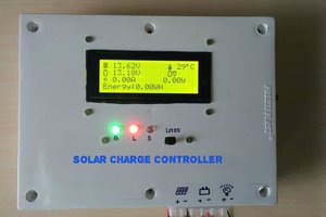
Why use a MOSFET driver when the arduino can drive a IRL540 directly?

  Are you sure? yes | no

magimahesh3198 wrote 08/05/2020 at 06:40 point

hello , are the IR2104 ouputs pulses are proper?

if yes can you send me snap of it.

  Are you sure? yes | no

perrinboys wrote 10/19/2019 at 22:07 point

Hey how can i donate $$$

  Are you sure? yes | no

welbertj wrote 08/29/2019 at 02:12 point

ola Debasish Dutta
eu preciso de sua ajuda no projeto 3.1
Eu não posso ler a corrente corretamente para acs712 a 30A

pode me ajudar
// escalando para implementação de inteiro
   #define battery_voltage_scale 45500 // (5V * (150 + 20) / 20) // R1 = 100k e R2 = 20K Leitura da escala completa em milivolts
   #define solar_voltage_scale 45500 // (5V * ((150 + 20) / 20) // R1 = 150k e R2 = 20K Leitura da escala completa em milivolts
   // # define a escala de corrente 27027 // 5A --- 5V / 0,185 * 1000 - leitura da escala completa em mili ampères
   #define current_scale 7575 // 30A --- 5V / 0,66 * 1000 - leitura em escala completa em mili ampères
   #define current_offset 5097 // configuração para obter corrente medida zero quando a corrente é zero
   // # define current_offset 3939 // ajuste para obter corrente medida zero quando a corrente é zero
   #define DCMCCM 5 // fração da corrente máxima para troca entre o DCM e o CCM (por exemplo, 20% para 5)

  Are you sure? yes | no

padmasreenagarajan wrote 12/07/2018 at 12:50 point

Hi all, I'm a final year student. 

I'm interested in doing MPPT solar charge controller project. Could you please help me out? 

  Are you sure? yes | no

murray wrote 07/24/2018 at 09:56 point

Hi there. One area where you simplify the design is in the measurements.

We need to know the output voltage to make sure we don't  over charge the batteries, and we need to measure the output current, but that is about all. The exact input power is irrelevant, simply optimize for maximum output current, what you want is maximum output current up to the max charge voltage.

  Are you sure? yes | no

satcom wrote 02/04/2018 at 11:30 point

Hi Debashish,

I am a student and very interest in this project. I would like to consult with you that the V3.1 whether a completed and working charger? Thank you! 

  Are you sure? yes | no

Sayandeep Nayak wrote 10/31/2017 at 07:40 point

Hi Debashish,

I just subscribed and followed you on youtube and instructables. Congratulation on your success in some contests. I also am from Odisha. Kemiti achanti apana?

  Are you sure? yes | no

Nikos wrote 04/15/2017 at 20:31 point

Hi,

great project and congratulations for the awards you have won!

One question that is bothering me, since I am also currently working on a power meter project for solar systems.

The buck controller is obviously using PWM pulses to charge the battery. My question is, how is it possible to sense such a current with the ACS712 sensor since it is not constant? Do you notice in your measurements that the current is not constant? Or do I have to assume that the sensor is measuring the RMS current?

  Are you sure? yes | no

vitalijbojko wrote 03/25/2017 at 06:29 point

A good circuit Not all 12 volt batteries. It would be nice to upgrade the code 12-24 to 48 volts.

  Are you sure? yes | no

Shane wrote 01/10/2017 at 01:09 point

I am about to embark on a similar project but will be using an XRP7704 Buck controller.  This chip has an I2C interface to talk to an Arduino, and 4-phase conversion for reduced input and output ripple currents.  For drivers, I will use the ISL99135b which has level shift and 35A half-bridge drivers in one package.  The Arduino will not only continuously "hunt" for MPPT, but also monitor battery health for display.

  I suspect that a reasonably constant current from the PVs is necessary to maximise power.  Alternatively, a large capacitor connected to the panel, but then, inrush current control may become necessary.  If the average current is at the MPPT, the actual panel voltage will swing substantially above and below that point.

  Are you sure? yes | no

Nicolás Rodríguez T wrote 08/11/2016 at 21:54 point

 Mr. Dutta,  after many hours trying to compile the software without success I've decided to stop it, fortunately I don't spend money. Unless you show that this project works, it's a fake!. In another web site you and your project has been  hardly criticized by the same reason. Apparently, no body could be able to run it satisfactorily.  End of the story.

  Are you sure? yes | no

tom.starwalker wrote 07/23/2016 at 10:37 point

So if I want to customize this for Li-ion batteries rated at 24V/25A, I'll just change the parameters in the code made for Arduino regarding voltage rating? Do I need stronger MOSFET's too?

  Are you sure? yes | no

guy caluwaerts wrote 04/27/2016 at 19:46 point

meanwhile I started with a prototype board to built the controller. It's gone be the 10A version.

I have some questions about the coils.  In the description and also on the drawings 33 micro H is  indicated. When I see the component list, there are other values (135 µH for 5A, 45 µH for the 10 version.. Is this correct ? I will not make the coil myself but order it.

  Are you sure? yes | no

Jose Pedro R. A. Ribeiro wrote 02/26/2016 at 21:40 point

use charge controller would be more economical (photovoltaic system)

  Are you sure? yes | no

guy caluwaerts wrote 02/23/2016 at 10:27 point

I'm interested in your project.  I'm making a solar tracker for my camper with a  solar panel of 80 Watt. So I think I have to go for the 8A version. Where can I order the PCB or see the latest drawing of this version ?

  Are you sure? yes | no

phbo0303 wrote 12/16/2015 at 10:00 point

Hi,

I am interested in your project! I want to know basic question. Why connected in parallel R2 and C8??? I am beginner of electric circuit. Can you tell me the reason??

  Are you sure? yes | no

bandi94 wrote 12/18/2015 at 08:05 point

R1 and R2 are in series and it's called voltage divider. The Arduino can't take on the input more than 5V so R1 and R2 are dividing solar panel voltage down to 0-5V for the arduino. C8 is a filtering capacitor to filter out any noise so arduino can measure the voltage without error. 

  Are you sure? yes | no

phbo0303 wrote 12/21/2015 at 01:49 point

Hi,
Thank you for your reply! It was good for me!

  Are you sure? yes | no

[deleted]

[this comment has been deleted]

bandi94 wrote 12/09/2015 at 13:07 point

Bootstrap capacitor is failing in every possible way, i already noticed Deba about it but i don't know if he is going to do something about it. IR2104 is a load driver and not a battery charger, When you drive a load and Q2 switches off on Source pin you will have 0V so the voltage potential of the bootstrap cap. is input voltage - 0V = input voltage so that mean's it can double the voltage on the drain pin, but if you put a battery on the load side when Q2 is off you have battery voltage on Source pin and not 0V so potential = input-battery that means  18V(solarV) - 12(batteryV) = 6V on the bootstrap cap and it's not even near the minimum 8Vgs that Q2 will generate a lot of heat.  The right way to do it is a voltage doubler aka Dickson charge pump, or galvanic isolated power supply in range of 10-15V (this can be a battery,a simple 12V screwdriver charger,a small 12V transformer that can supply 10-15mA,etc..), and a push-pull gate driver(made with transistors) or an opto-isolated gate driver (TLP250). 

  Are you sure? yes | no

Lars Sorensen wrote 10/30/2015 at 21:05 point

Hi guys. How are you and the project (v4) going?

Is it still ongoing are you taking a break?

  Are you sure? yes | no

Open Green Energy wrote 11/04/2015 at 09:44 point

Hello Lars,

We are taking some time break due to busy on other work.Stay in touch we will start it again.

  Are you sure? yes | no

Evan Allen wrote 10/23/2015 at 14:58 point

Would spec-ing up some of the components allow for things like 60Voc panels, or is this limited to lower voltage panels by some specific design choices?

  Are you sure? yes | no

bandi94 wrote 10/25/2015 at 16:58 point

It is possible to make it work with 60Voc but there is no logic to convert 60V panels to 12V battery. You would need 4x12V battery to work at 48V battery bank. At 48V battery bank you would have some problems with IR2104 max Vcc 25V so the mosfet driver needs a voltage regulator, heavy duty Mosfet's that can handle the 60V drain-source voltage, and so on.  Now converting 60V to 12V will work with replacing the mosfets (IRFZ44N max is 55V) capacitors etc.. but you will have serious problems on the inductor, you would reduce the voltage from 60V to 12V that is 5 times the input and the inductor will work very hard so you would need a very big core with very thick wire to handle the generated heat. Anyway until they don't fix the Q3 shorting out the battery(and i am very intrested how they will fix it from the moment that sync. buck is not made for battery charging) the charger doesn't really work in this configuration, you would need to re-design it with a standard async buck replacing Q3 with a schottky diode.

  Are you sure? yes | no

bandi94 wrote 12/11/2015 at 08:36 point

Yes replacing it with a diode would decrease the efficiency, but the current status of the charger does not handle Q3 very well and the loss is even higher than with a diode. If Q3 stays open even few millis longer it will short the battery losing a lot of power on Q3. I asked somebody who build it and told me that he got 3 Q3's burnt out and he need a fan to cool it down even with a big heatsink. A good schottky diode drops about 0.4V, when i charged a 56Ah battery at 4A Q1 and the schottky diode had a small heatsink and no problem with heating up. So i am just curious which is better ? Q3 with a big heatsink and a fan, or a schotty which needs a very small heatsink and does not even heat-up ?   I agree that you loss power but to use Q3 you need a complex system to drive it and not just a "homemade" circuit with a poor IR2104. 

  Are you sure? yes | no

Similar Projects

Does this project spark your interest?

Become a member to follow this project and never miss any updates