 Jonathan Cline IEEE
This paper details the design and construction of a simple data acquisition and plotting system for amateur or commercial use. The system uses a general purpose computer, a standardized USB-powered peripheral board, and small software application to measure, record, and plot a real time signal. The system is demonstrated in use with a biochemistry chromatography experiment; however, the system may be used in conjunction with any experiment which needs to measure and plot an electrical signal. Modifications to the hardware are discussed to adapt the circuit to various signal voltages. Total cost is about US $35 in parts, a few hours connecting common electronic components with a soldering iron, and a few hours entering software on any typical computer. This system does require a separate computer which supports USB, although a small, inexpensive, embedded computer may be substituted instead, such as the popular Raspberry Pi board (currently, US $25). In contrast, a commercial-grade chart recorder which performs the same functions might have a price tag of US $2,000. Building this basic data acquisition system also yields the understanding of how to design and use such systems, either for use in laboratory protocols, or in field experiments.
0%
0%
Simple Data Acquisition and Plotting for Wetware
My O'Reilly Biocoder article, A Simple Data Acquisition and Plotting System for Low Cost Experimentation.
Become a Hackaday.io member
Already have an account? Log in.
Just one more thing
To make the experience fit your profile, pick a username and tell us what interests you.
Pick an awesome username
hackaday.io/
Your profile's URL: hackaday.io/username. Max 25 alphanumeric characters.
Pick a few interests
Projects that share your interests
People that share your interests

 Al Williams
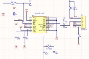
 hesam.moshiri
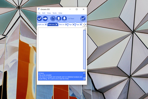
 Simon Tsaoussis
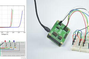
 Kuldeep Singh Dhaka