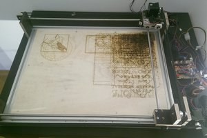
Close
0%
0%

Yet another laser engraver / cutter

I build a 1.6 W 450 nm laser cutter / engraver mostly from China parts.

Similar projects worth following

Facts

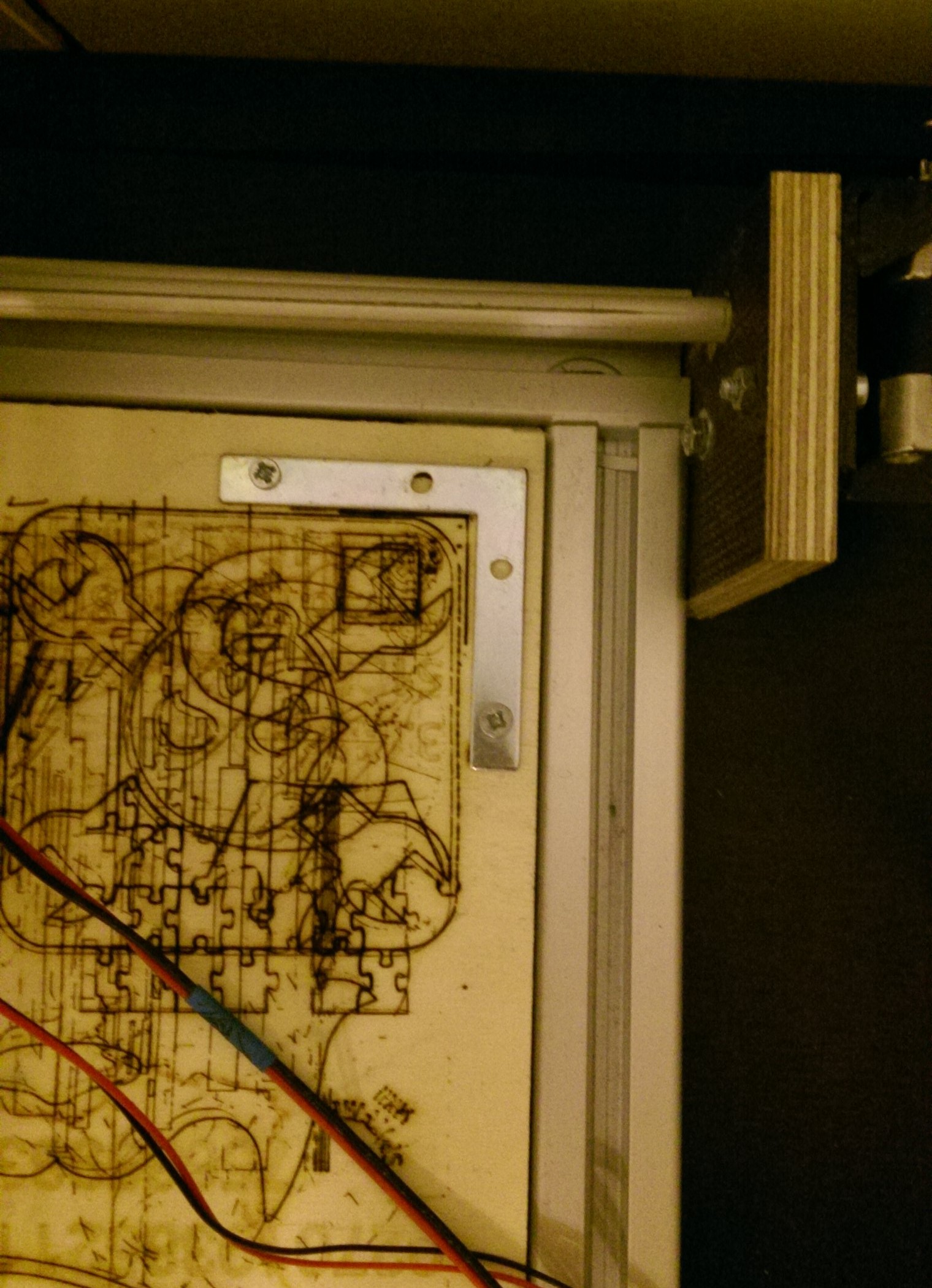
  • Working area: 560 x 411 mm
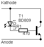
  • Laser: 1.6 W_opt. Osram PL TB450B diode, 450 nm, with a heat sink
  • Motors: China brand Nema17, max. 1.2A running at < 1A
  • Motor driver: A4988, China knock-off
  • MCU: China Arduino Pro mini compatible
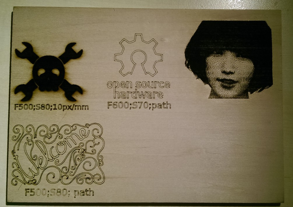
  • Software: Universal G-Codesender 1.8, GRBL 0.9g / 0.9i, X-Loader, Inkscape 0.48.5, Laserengraver-plugin
  • 1500 mm/min for jogging motion, usual feed rates of 80-250 mm/min
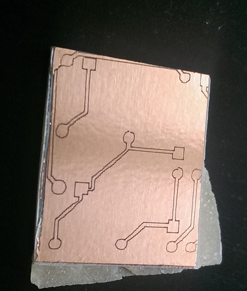
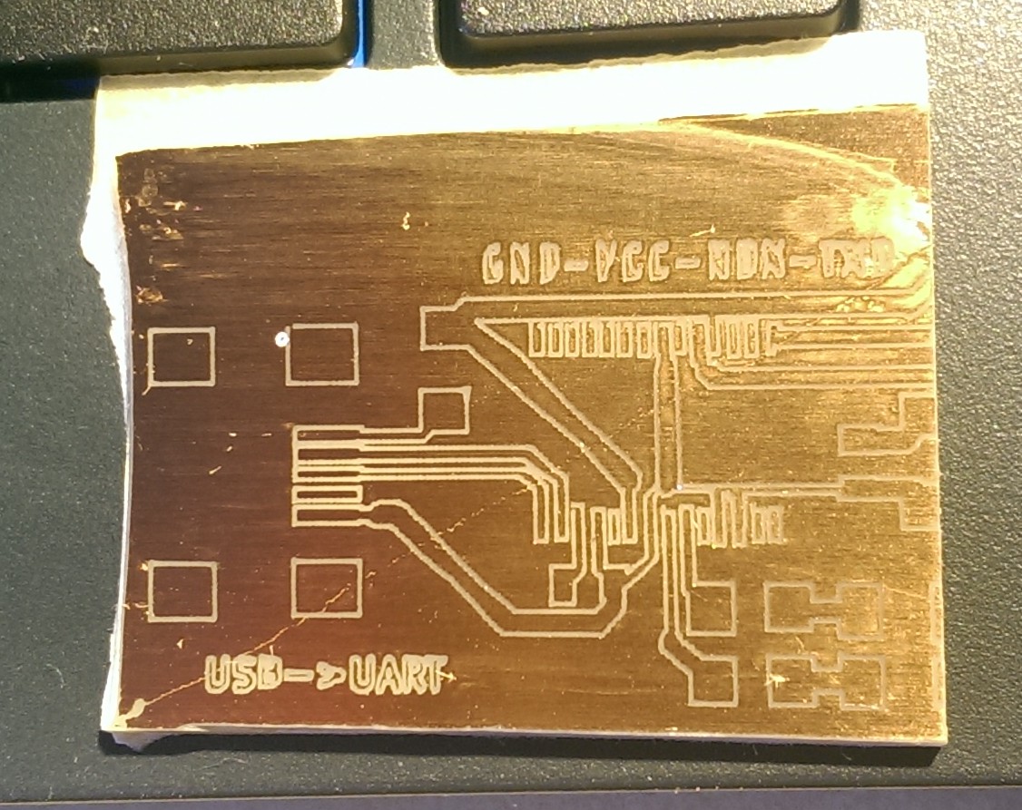
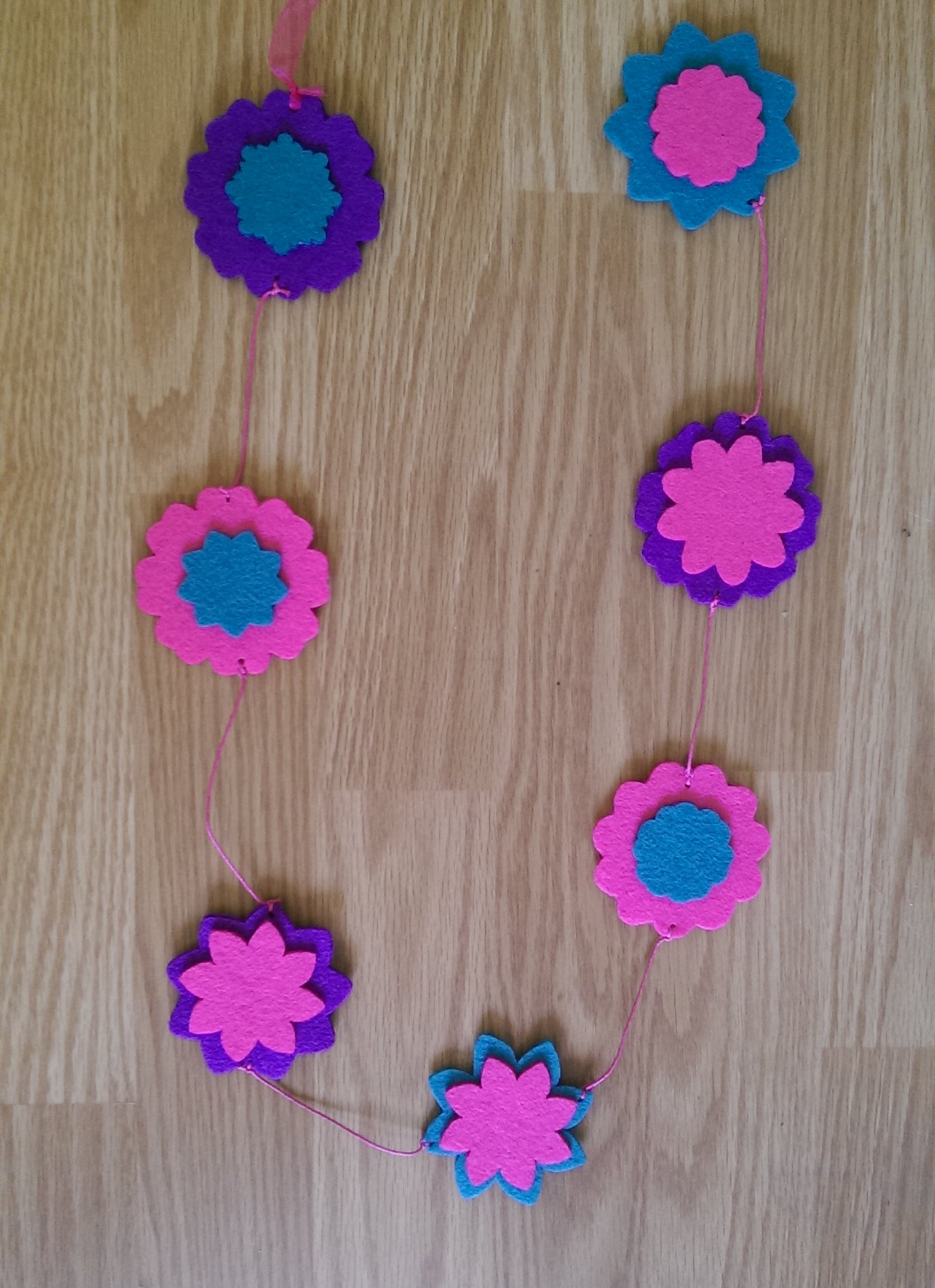
  • Cuts white and coloured paper, coloured foam, felt, engraves thick cupboard and wood

  • 4 × LMUU8, 8mm linear bearings
  • 3 × Nema 17 motor mount
  • 6 × GT-2 timing belt, 20 teeth
  • 1 × GT-2 pulley, 20 teeth
  • 3 × China brand Nema 17 motors, max. 1.2 A @ 2.4V, 40 Nm/cm

View all 16 components

  • PCBs with an UV-laser

    dechemist05/02/2016 at 17:46 0 comments

    Recently I bought a 100 mW UV laser module (405 nm) with power supply (TTL capable) on eBay from laserlands.com to plot PCBs on a printed circuit board with a photo sensitive layer on it. To develop the photosensitive layer 10 - 20 mW of laser power with a feed rate of 300 mm /min is sufficient. I just bought the 100 mW laser because it already came with the TTL-capable power supply.

    The first results looked promising: The lines are about 0.2 - 0.4 mm wide after removal of the photo layer with NaOH and etching with HCl / H2O2. But soon I experienced problems when it came to plot very tiny structures.

    As you can see in the picture on the right, the squares (SMD SOP28 IC, 0.5 mm pitch) are not uniform. This is because my mechanics are to inaccurate / to wobbly. So as a pragmatic person I planed to build a new, more accurate plotter. The process is describes here: yet-another-laser-engraver-cutter-2

    This project page will no longer be updated. All new developments will be documented on the new page.

  • The contest is on ! :)

    dechemist02/22/2016 at 19:10 0 comments
  • To little current...

    dechemist02/08/2016 at 18:34 0 comments

    While I was playing with my laser plotter this weekend and again wondering why some materials were not cut as good as I expected, a thought came into my mind: I should measure the output current of the laser power supply, maybe that is the reason....And then it hit me, the laser diode was running at only 4V and 320 mA instead of 1.4 A ! Shame on me !

    I have no idea why the current was so low, I guess I did not remember correctly and assumed that I chose the correct settings when I build it, but apparently I did not.

    After I set the current to 1.4 A I realized the real power of this beast !

    Fabric, 5 mm felt, paper, 2.5 mm dense cardboard etc. were cut like a hot knife through butter with feed rates up to 500 mm / min ! That is about 5 times faster that before.

    With this impressive power in hand I then realized that I have a new problem: All my settings (laser power / feed rate) were wrong (ok ok 1st. world problems ^^).

    I then tested the diode with a new material I came in touch with at the Makerfair in Munich: Kraftplex It is a 'wooden sheeting' made entirely out of wood. I got the business card of one of the inventors (which was made out of Kraftplex 1.5 mm) and tried to cut a square out of it (S100;F40) and it worked like a charm ! The other business card with 0.8 mm thickness worked even better.

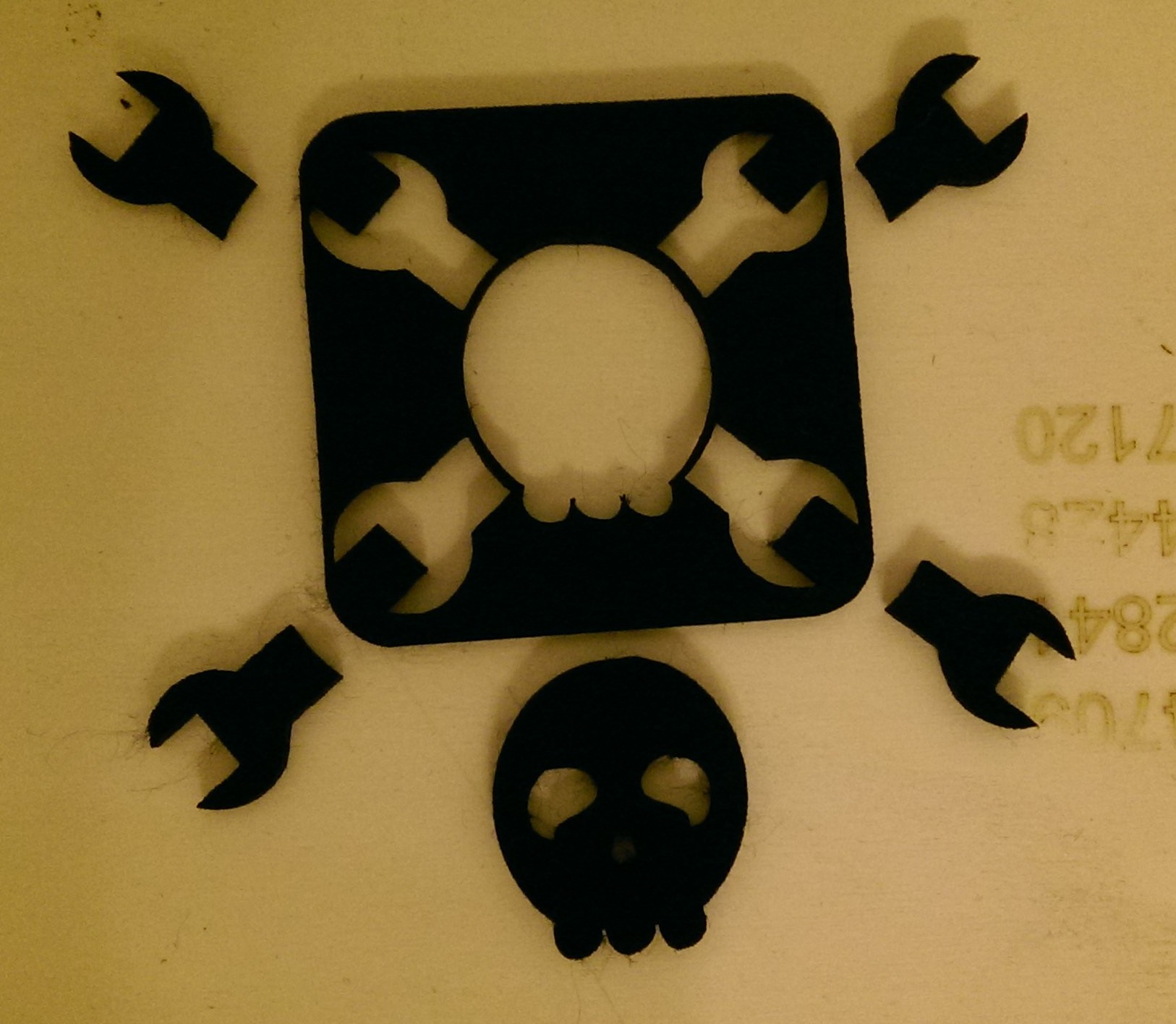
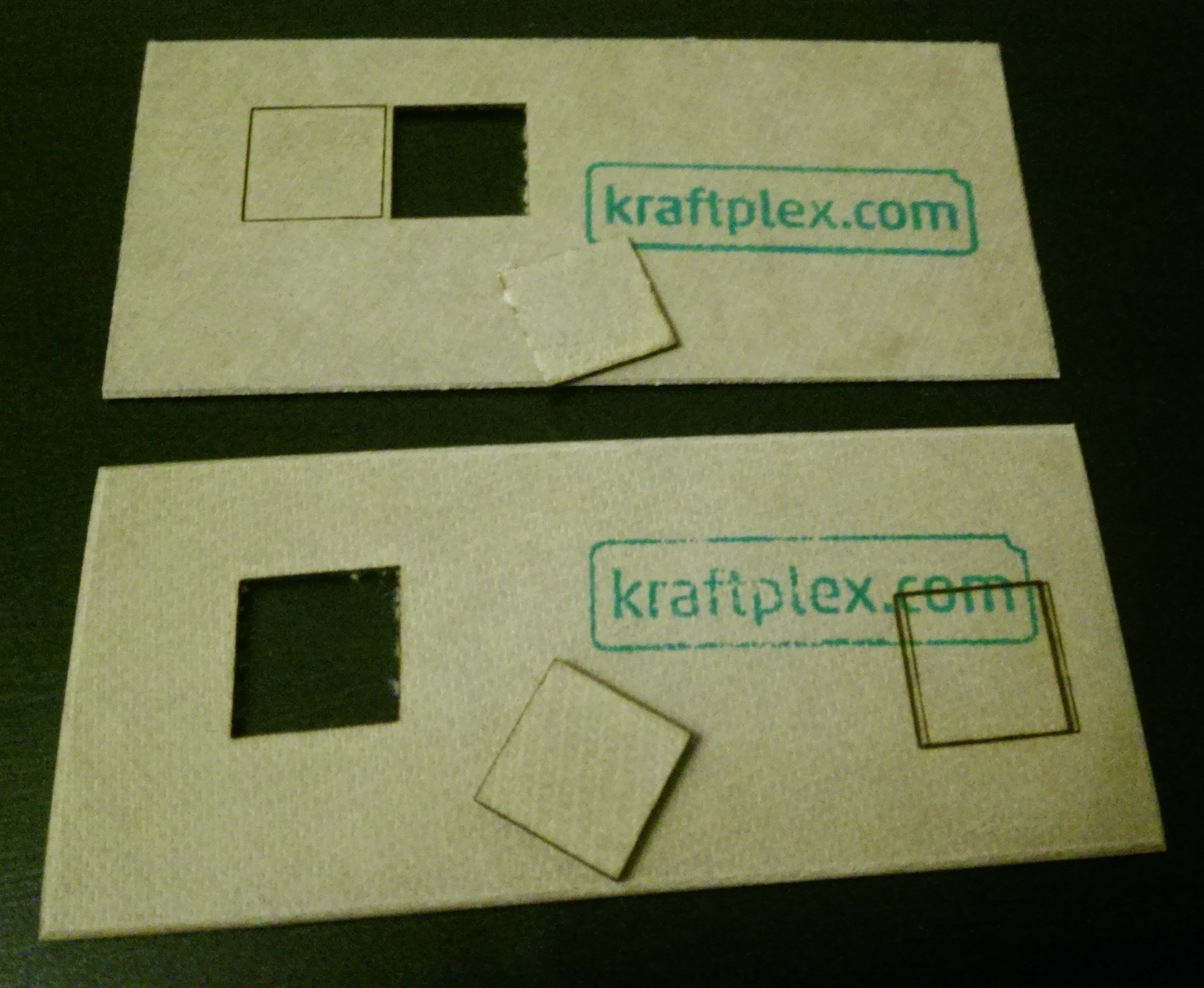
    Top: 0.8 mm Kraftplex, bottom: 1.5 mm. The second burned in square is from the first attempt to cut it with the lower current.
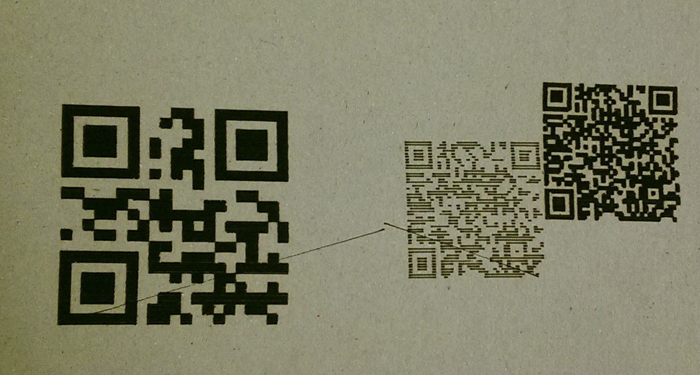
  • Yet another laser plotter meets Raster 2 Laser GCode generator

    dechemist12/14/2015 at 20:26 0 comments

    A view days back I found again a plugin here on hackaday.io, the "Raster 2 Laser GCode generator". It is a plugin for Inkscape to generate Gcode from images files like jpg, svg and png in different styles for laser engraving !

    I testet it with some QRcode-images, and here are the results:

    I engraved them on very thick and dense cupboard:

    From left to right (1: 50 x 50 mm, 5 px / mm, S100, F200; 2: 30 x 30 mm, 2 px / mm, S100, F250; 3: 30 x 30 mm, 5 px / mm, S100, F250; 3)

    As you can see, the 5 px / mm setting results in nice dark blocks. The lower setting on the other hand gives visible spaces in the dark blocks. This QRcode could not be read by my smart phone. The other two work nicely.

    In the next tests I will attempt to make tiny (10 x 10 mm) codes on cupboard or wood...

  • Creative weekend

    dechemist04/27/2015 at 20:05 0 comments

    This was a quite creative weekend. I experimented a bit with thick felt (4 mm, S100, <= F50) and cut some flowers for decoration from it :)

    A nice engraving on a birthday card for little princesses ^^

    And finall the logo out of 4 mm black felt (S100, F30) we all blog and build for HACKADAY !

    I added a metal elbow at the 0/0 position to have a easier alignment of the workpiece on my plotter.

View all 5 project logs

  • 1
    Step 1

    The frame


  • 2
    Step 2

    Axis


  • 3
    Step 3

    Laser-module and driver

    For the laser module I choose a relatively cheep heat sink and a standard 3-layer glass lens (450 nm) and a Osram PL TB450B 1.6 W_opt. 450 nm diode from China. The lens came in a package with the heat sink.

    As the power source for the laser I am using a constant current power supply (max. 3W) with TTL support.

    First I had to unsolder all plastic sockets from the board since I could not find the matching connectors online. I replaced them with common 2-pol Molex sockets and made my own connectors with cables.

    To adjust the current the laser will get, I adopted the idea of a dummy diode from power-LEDs (dummy LEDs).

    A BD809 was mounted on a good heat sink and a 20 mA LED + 470 ohm resistor was soldered to base and collector of the transistor.

    With this dummy laser diode I could adjust the current without risking my Osram diode. The transistor converts all energy into heat, so with 1.2 A @ about 4.2 V which are typical parameters for the laser diode it generated

    about 5W of head. There is no arguing about whether that a heat sink is necessary !

    To switch the laser on/off by grbl, I connected the TTL- pin to a common ground with the arduino and the TTL+ pin with a pull-down resisitor to pin11 (grbl 0.9) of the arduino. By variating the spindle spped with the S<number> g-code paramter a PWM signal controls the on/off time of the laser and resulting in <number> % of power.

    With the power source set up, I began to mount the diode itself into the heat sink. This was more difficult than I thought since there is very little space for the cables and the isolation of the pins.

    With the cables finally soldered to the diode, I applyed a tiny amount of silver thermal paste to the diode. The data sheet states, that the main heat dissipation is done by the tiny metal ring around the diode.

    I wanted to be sure the diode runs within thermal parameters (>70 °C).

    For active cooling I removed the fan that came with the laser heat sink and mounted a very powerful 4 cm fan on it. This fan not only cools the laser, but also blow all smoke from cutting/engraving away.

    So nothing can condensate on the glass lens.

View all 7 instructions

Enjoy this project?

Share

Discussions

morviaan wrote 05/17/2016 at 14:07 point

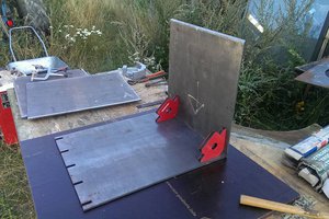
Hi, I've notice you use Laserengraver-plugin for inkspace, I've read somewhere in this forum, you also tryed Raster 2 Laser. Which you liked the most? Which is better?


Thank you

  Are you sure? yes | no

Similar Projects

Does this project spark your interest?

Become a member to follow this project and never miss any updates