 Beamsjr
Code: https://github.com/beamsjr/Arduino_CC3000_FluxCapacitor
0%
0%
Wireless Flux Capacitor
A networked flux capacitor status indicator.
Become a Hackaday.io member
Already have an account? Log in.
Just one more thing
To make the experience fit your profile, pick a username and tell us what interests you.
Pick an awesome username
hackaday.io/
Your profile's URL: hackaday.io/username. Max 25 alphanumeric characters.
Pick a few interests
Projects that share your interests
People that share your interests
 Then I threw together the top part of the case and cut it out of MDF, a little sanding and its ready for primer.
  I think im going to paint the case grey like the "real" flux capacitor. What do you think?


 brandon
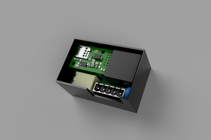
 Nicolò
 matt venn
 testudor | Jakob
Awesome project!