 smashedagainst
Prototyping began with a typical Arduino Uno and once the design finalized, I chose to use the Pro Mini which saves space. Also, the Rugged Motor Driver shield has mods from previous projects (reassigning pins), so it was easiest to use the driver board in standalone mode via the green 6 way terminal block.
When supplying the Arduino from USB power, the sketch and driver behavior was different than when only running off the 5V input coming from the power supply I scavenged from a laser printer (details in build log). It irks me when this happens as my projects tend to be stand-alone and I like to power them from typical 5V supplies. So I desoldered the fuse next to the Uno's USB jack. Now the Arduino is fed from the 5V I want to give it and behaves properly when troubleshooting on serial over usb.
None of the parts in this project get hot, so I was able to box everything up nicely without cooling concerns. The Rugged shield's two driver chips eventually become warm to the touch. When trying the other driver hardware, quite a bit of heat would be generated. The stepper never got warm, so it's up to the task.
Once the electrics and control were proven, I worked on the mechanical design. There was some iteration; I needed to see that the stepper could hold the shaft firmly enough that I could use an end-mill on its aluminum arbor without the shaft moving. Only the Rugged shield was able to accomplish this.
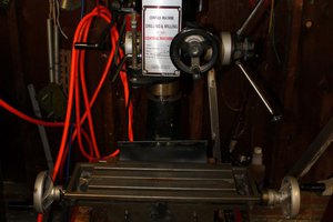
The arbor fixed to the stepper has a hex head that wedges into the parts we will be machining. Read the mechanicals entry of the build log for details, but the parts to the right firmly clamp the part to be machined to the stepper's arbor while allowing the part to rotate with the arbor.
Note that this isn't "NC" as the stepper is not moving against the cutting tool, it is used to automate part positioning between machining operations, which will be performed manually by the operator.
We finally got in the parts and I was able to try out this tool -- it worked great! I expected the pieces to need some adjustments or repositioning. I might not have tightened the screws enough on the outer cylinder and side plate, so as they worked loose, I noticed these pieces shifting when I clamped and unclamped parts. Also contributing to the screws loosening could be if/when the drill chatters. This makes pretty strong vibrations. I ended up running the spindle at 2400 rpm and when the drilling is started without hesitation, there is no chatter. The "drill bit" is actually a Size 5 countersink.
Got through the first hundred parts in under 2 hours. Not seen in the video, the parts coming out of the tool are well over 100 degrees, so I added air cooling pointing where the countersink hits the part. After turning up the spindle to 2400 rpm, I got into a good rhythm and was cranking out the parts much quicker than in the video. I used the yellow spray can (Maxima Multi Purpose Penetrant Lubricant - MPPL) between each part, sprayed at the countersink as I started the first cut. The countersink is double ended and should get me through the remaining 400 parts.


 Alastair Young
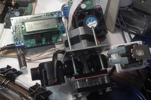
 James Newton
 Dillon Nichols