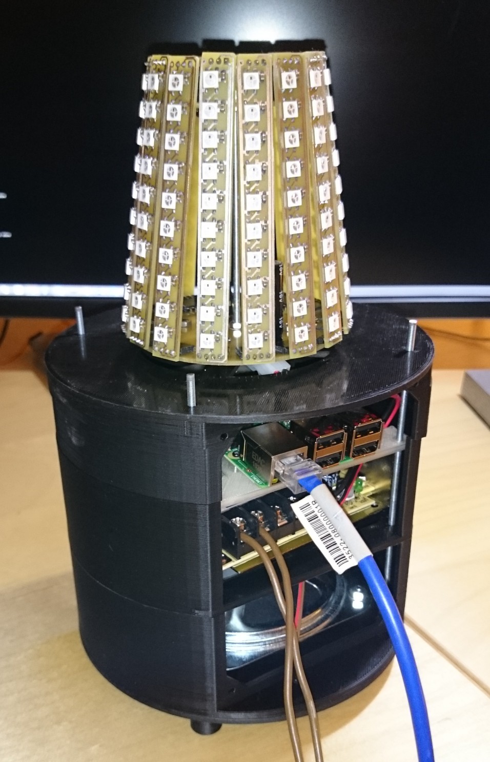
• Change of concept

    SUF01/04/2016 at 22:06 0 comments

    It is been a while since I didn't write about this project. I've been working heavily on it in the last weeks, so it is now in the finish line.

    Change of concept:

    When I started to work on it I wanted to build upon the Freescale ethernet capable Kinetis platform. It turned out, that my lack of knowledge/time/etc. will not allow me to finish it in the near future. I counted how many things needs to be implemented to get it working (DHCP, http client, SSL, auth, neopixel, JSON/XML processing, etc.)

    It looked to much effort. So I switched the platform to BeagleBone Black first, than Raspbery PI 2.

    First I wanted to buy some rectangular enclosure, but finally I went to a home grown (3D Printed) circular enclosure.

    Originally I wanted to order the PCBs for the lighting, finally I etched, soldered all of them (all together 18 pieces) at home.

    The plan for the programming language was C. It became Python.

    The current state of the project looks like this:

    And most of the software is already working (but the software parts are working just separately right now). I'm able to extract the information from the build server, generate some noise, and the lights are working. Here is the test of the later one:

    A few things left:

    - Cabling the audio part

    - Finis the mains cabling

    - Printing (3D) the back cover of the enclosure

    - Printing (3D) the parts holding the "flower pot"

    - Finishing the software

  • "Flowerpot"

    SUF08/03/2015 at 04:10 0 comments

    During the time I was thinking about this project there was always a question, what kind of cap should I use for it.

    I went through many stores, trying to find a drinking glass (from glass or plastic) what could be suitable. Found nothing, even I was thinking about 3D printing it from some kind of transparent material, but the cost was high.

    You never know, where can you find a solution for a problem.

    I was on vacation in the recent weeks. When I was looking around in a gadget shop in Copenhagen, I found this:

    I don't know, what it is, most probably a glass flowerpot. Honestly I don't care, what the original purpose of it. It will serve as the cap for my project.

    Additionally, yesterday Erich Styger of MCUONECLIPSE, started to write a blog series on connecting Adafruit Neopoixels to the FRDM-K64F board:

    http://mcuoneclipse.com/2015/08/01/tutorial-adafruit-ws2812b-neopixels-with-the-freescale-frdm-k64f-board-part-1-hardware/

    I'm very happy about it. It will save me lot of time writing the code for this project.

  • Lightbar

    SUF07/23/2015 at 05:00 0 comments

    This is not a new project. At least not for me, it is just entered into the Hackaday.io recently.

    This project log is about the lighting part of the project.

    I started to design and built it almost a year ago. The orginal idea was the following:

    build a 48 chanel LED controller (16 RGB channels) around a TI TLC5955, and drive the 16 LED strips from it.

    This means that the LEDs in the strips are connected in serial, need "high voltage" (36V) and not individualy adressible. I went even further. Built the controller and 10 out of the 16 LED bars.

    And the project was abandoned here. I not even tried the controller out (this is because my regular fear to switch on something I built first time). The project was lying around in its project box until recently. I was mainly working on my CNC Motor controller.

    This project had a "deadline" few weeks before it, I restarted to work on it (even knowing that I clearly will miss the deadline). I realized, that the TLC5955 based driver is not a good idea:

    - The LEDs are not individualy addressible

    - There is no software library/sample code availiable what I can build uppon

    - Two channel power supply needed (36V, 5V) for the whole device

    So I switched to the common WS2812B LEDs.

    Downloaded the chip's datasheet from Adafruit, and designed the lightbar. Even I almost etched the boards. (Un)fortunately I wasn't able to create a good etching mask on the first two try, so the copper clad board was lying around on my desk for a while.

    Then the ordered chips arrived. Opened the first one and a big surprise blown into my face. This LEDs has 4 pins, I expected 6.

    What they sent??? ...

    ...exactly what I ordered.

    I wasn't care about the meaning of the B at the end of the chip marking. The datasheet what I downloaded is for the WS2812 and not the WS2812B. Great.

    Redesigned the board. This time I gave up the idea to put all of the light bars on a single rather large board. Intead made two designs:

    - One for the home grown PCB

    - One for the PCB shop

    I built the one on the home PCB for testig.

    And I want to order the final version.

    The reasons why I didn't done it yet:

    I've an old design, from one of my old projects, where I made a mistake and the board should be reordered. The lightbar design need 26x100mm board space (two of it, adds to 20 pieces). This design need 50x100mm. This two can be easily combined, and the cost is the 100x100mm boards cost anyway. Even I already added them to a single board (there is three lightbars, but I just need two).

    My dilema:

    - If I add just two lightbars, a 20x100mm area left what can be used for the USB Booster, when I can come up with a new design

    - Black or White? I would use white for the lightbars because of the additional reflection. I would use green or black for the additional panel, but definetly not White.

    It would be great if the boards arrive soon, but I can't work on the USB Booster before August...