 unfoundbug
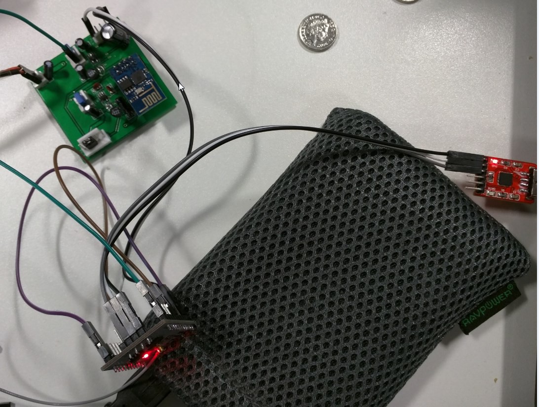
The board is a WiFi enabled interface board, that I am designing to be small but able to control a wide variety of devices, an ESP8266 does the heavy lifting, providing WiFi interaction, a web server (for configuration and control) and some GPIO, this is also connected to a second microcontroller, the PIC12LF1552 from microchip, small footprint, and a 32mhz crystal less clock means this can be doing something entirely independant of the main CPU, whether its running PWM, or bit-banging midi.
0%
0%
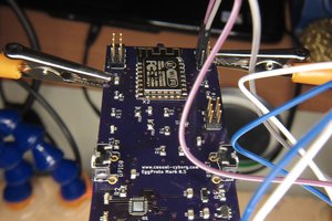
ESP8266 Parasite
A development board built to be able to go inside another project to enable wifi control
Become a Hackaday.io member
Already have an account? Log in.
Just one more thing
To make the experience fit your profile, pick a username and tell us what interests you.
Pick an awesome username
hackaday.io/
Your profile's URL: hackaday.io/username. Max 25 alphanumeric characters.
Pick a few interests
Projects that share your interests
People that share your interests


 Casual Cyborg
 Craig Hissett
 hebel23
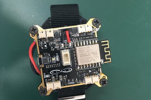
 Tanmay Karpe
nice