0%
0%
Auto-Parking Mecanum Robot
Making a robot with mecanum wheels, and having it Auto-Park
 Jack Najarian
Become a Hackaday.io member
Already have an account? Log in.
Just one more thing
To make the experience fit your profile, pick a username and tell us what interests you.
Pick an awesome username
hackaday.io/
Your profile's URL: hackaday.io/username. Max 25 alphanumeric characters.
Pick a few interests
Projects that share your interests
People that share your interests


 muzi
muzi
 Toni Paunovic
 Roald Lemmens
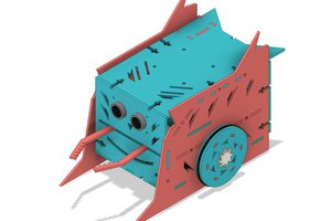
Which polyurethane product was used in the process?