 Retroplayer
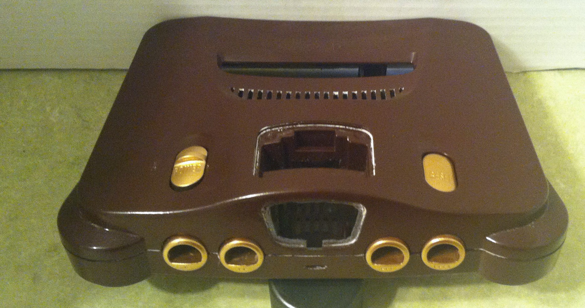
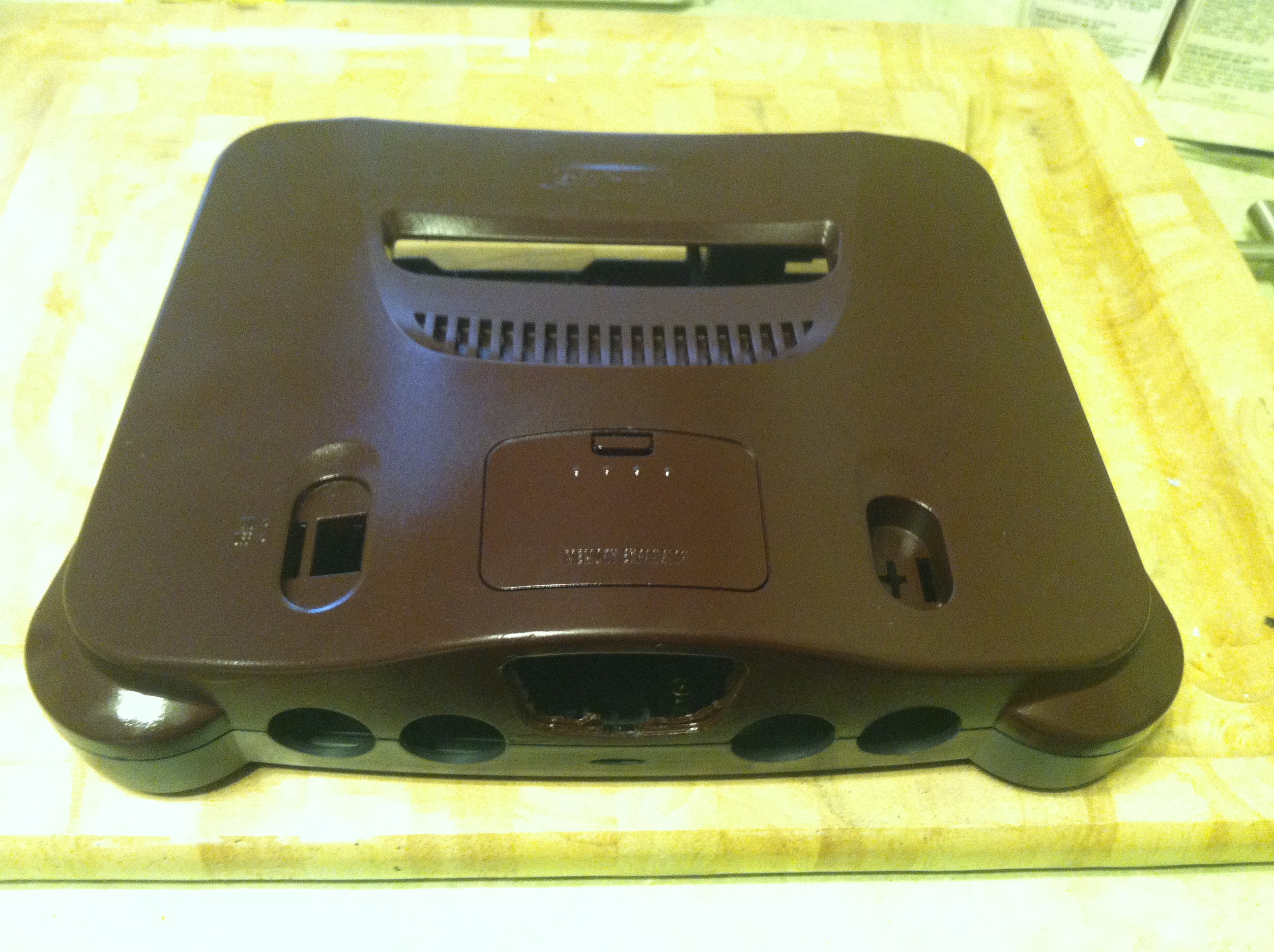
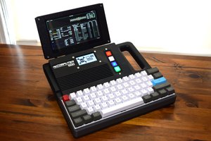
While looking around at the local electronics recycler, an N64 caught my eye. I realized that it looked an awful lot like an old radio. So, creativity struck.
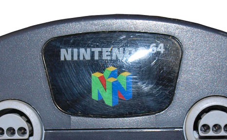
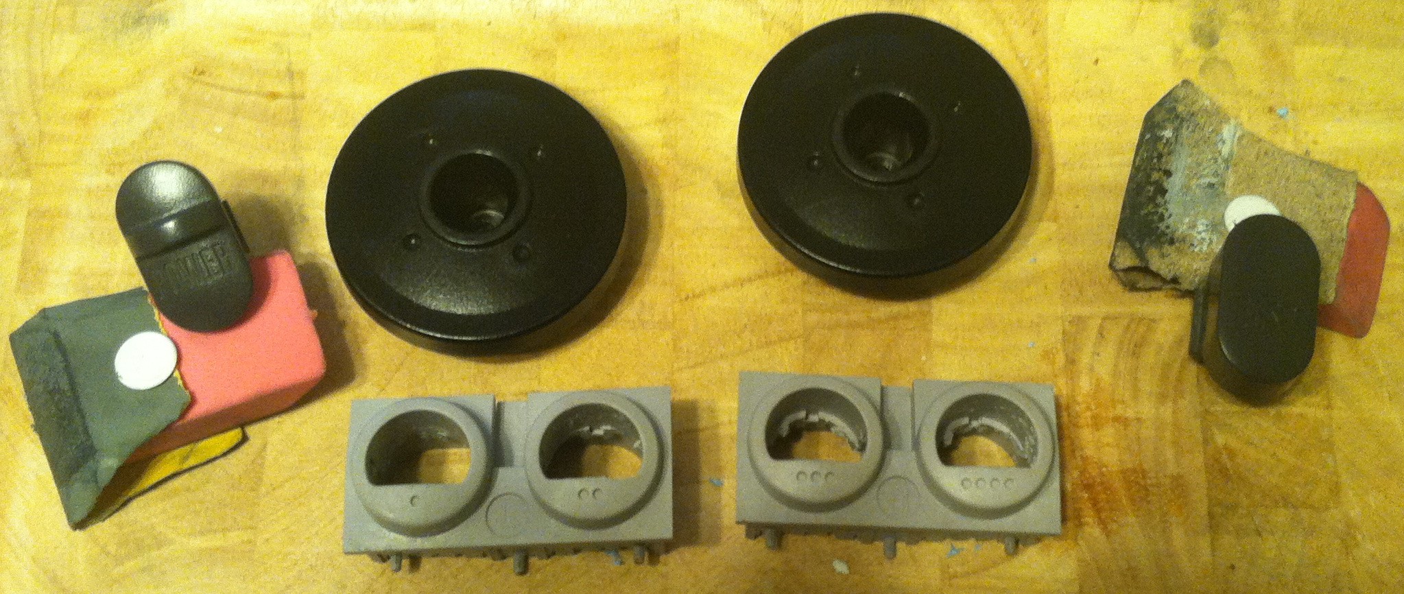
The Nintendo 64 logo on the front looks a radio dial, and the controller ports look like knobs. So this is where I begin.


 novak
novak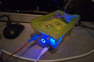
 Tom Nardi
 Magic Robots
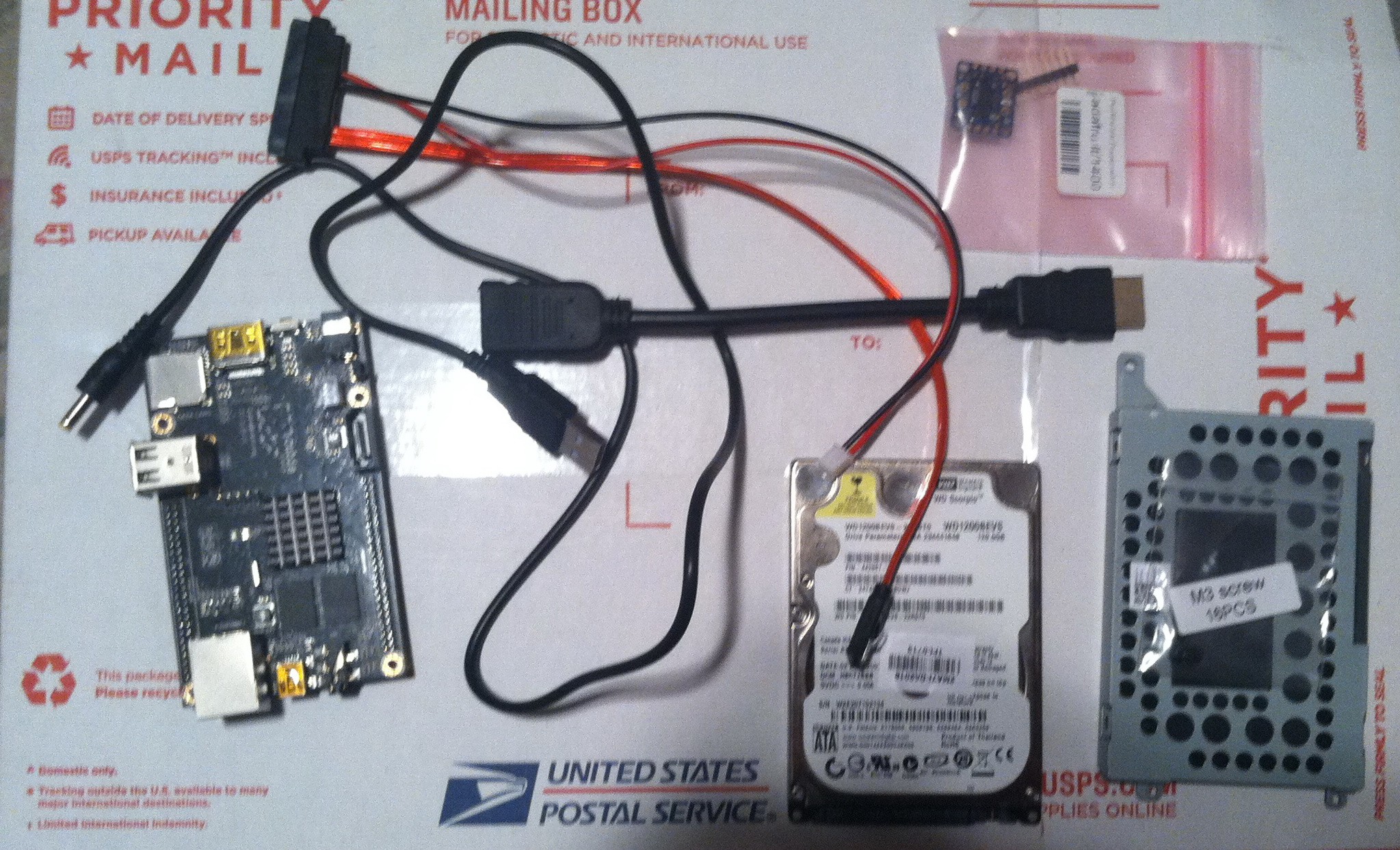
I am just learning linux and realize there is a steep learning curve here since there aren't currently any of these compiled for the cubieboard hardware and kernels yet. So a ton of work will be needed. However, most SW intended for the Raspberry Pi should run on this with some tweaking.