-
Transistor Amplifier
03/30/2020 at 08:04 • 0 commentsI designed an audio amplifier that can be made from general-purpose transistors (not needing VHF transistors that might cost more money) that are used for audio applications. You can make audio amplifiers with power amplifier ICs (integrated circuits) or operational amplifiers. However, most of those IC (integrated circuits) need voltages of at least 4.5 V.
You can make basic transistor amplifiers with:
1. Fixed bias.
2. Stabilised bias.
3. Feedback bias.
I tried the first and third biasing methods.
I made this circuit with BC559 BJT (Bipolar Junction) PNP transistors.
![]()
The only difference between BJT NPN and BJT PNP transistors is the direction of current conduction.
You can use the following NPN transistors:
- BC337, 2N2222, PN100
PNP transistors:
- BC327, 2N2907A
I included a small orange ceramic capacitor (about 10 nF) for the second transistor amplifier to filter high-frequency noise.
Step 1: Design the Circuit
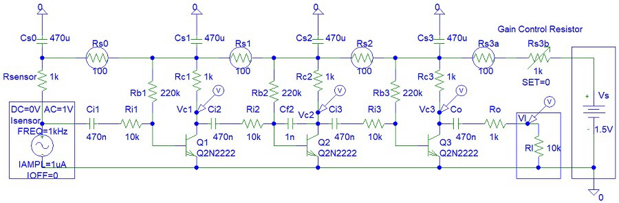
I have drawn the circuits in PSpice simulation software student edition version 9.1:
![]()
My circuit is useful for microphone and Line In amplification, will cost less money, and will last longer because I increased the resistor values to reduce the power dissipation.
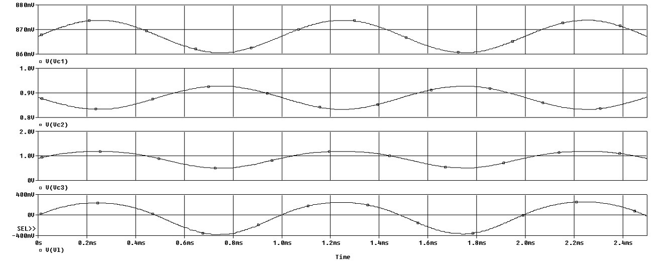
Step 2: Simulations
I used the old PSpice software to simulate the circuit.
![]()
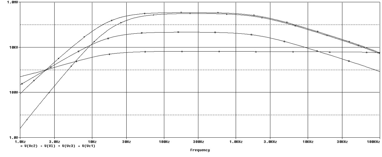
Frequency domain simulations:
![]()
Step 3: Build the Circuit
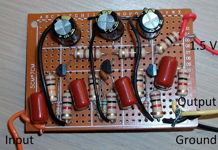
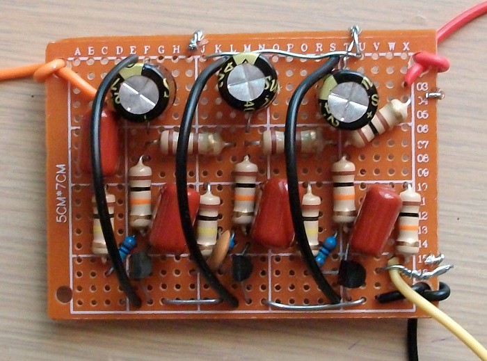
This photo is showing my transistor amplifier made with BJT NPN transistors:
![]()
I increased the Rc values to 10 kohms. I used a USB oscilloscope to test my circuit. Increasing the Rc values has increased the circuit gain but reduced the bandwidth to just 1 kHz due to transistor stray capacitance. I included a small orange ceramic capacitor (about 10 nF) for the second transistor amplifier to filter high-frequency noise.
Conclusion
Also, keep in mind that BC547, BC548, BC549, BC557, BC558, and BC559 are listed in the bad components project due to very low maximum power and maximum current ratings. Thus I suggest that you use other types of transistors.
-
Small Signal Motor Driver
03/29/2020 at 05:50 • 0 commentsThis article explains how you can build a small signal motor driver. A signal is entering the input of the circuit and is amplified with three transistors to drive a low current motor.
This circuit can be connected to an AC amplifier. The AC amplifier can be connected to a sensor that could be a:
- microphone,
- ultra-sonic sensor,
- infrared sensor,
- antenna.
Thus this circuit can cause the motor to move due to:
- sounds,
- ultra-sonic waves,
- infrared remote control transmission,
- radio waves.
I thought of the circuit fin this article after looking at the following Instructable:
https://www.instructables.com/id/Transistor-Light-Dimmer/
It is important to mention that the circuit can be implemented with just one MOSFET transistor. However, well-known MOSFETs are rare, MOSFETs cost more money and you might need to look for a MOSFET in your workshop inventory. Also, the MOSFET transistor would not allow you to control the current magnitude that controls the motor speed. In the circuit shown, the greater the magnitude of the input signal the faster the motor will spin. However, you can still control the speed of the motor with MOSFETs and Pulse Width Modulation (PWM) inputs: https://diyelectronics.webs.com/circuits.htm
Step 1: Design the Circuit
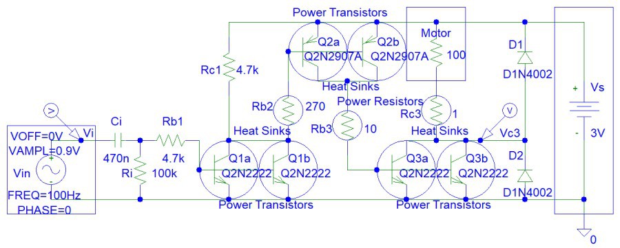
I have drawn the circuit in PSpice student edition version 9.1 software:
![]()
Calculate the maximum output current at worse case scenario. At worse case scenario transistor current gain, Beta = 20.
Ib1 = (Vin - Vbe3) / Rb1 = (3 V - 0.7 V) / 4.7 kohm = 2.3 V / 4700 ohms = 489.3617 uA
Ic1 = Ib1 * BetaMin = 489.3617 uA * 20 = 9.78723404 mA
Ib2 approximately equals to Ic1 because very little current is flowing through Rc1 resistor.:
Ic2 = Ic1 * BetaMin = 9.78723404 mA * 20 = 0.19574468085 A
Ic3 = Ic2 * BetaMin = 0.19574468085 A * 20 = 3.91489361702 A
Rc3 is 1 ohm and the transistor does not need to saturate. The maximum current is actually not 3.91489361702 A, but Vs / Rc3 = 3V / 1 ohm = 3 A < 3.91489361702 A (occurs when the motor is a short circuit if its movement is mechanically impeded or stopped), because the transistor saturates. However, you can achieve 3.91489361702 A output current if you raise the supply voltage to 4 V.
Now we can calculate the other resistors.
Rb2 = (Vin - Vbe2) / Ib2Max = (3 V - 0.7 V) / 9.78723404 mA
= 2.3 V / 9.78723404 mA = 235 ohms < (Rb2 || Rc1) = (270 ohms || 4700 ohms)
Rb3 = (Vin - Vbe3) / Ib3Max = (3 V - 0.7 V) / 0.19574468085 A
= 2.3 V / 0.19574468085 A = 11.75 ohms approximately 10 ohms
Rc1 and Ri resistors ensure that the circuit and the motor is OFF when the circuit is disconnected or when no input signal is applied.
Step 2: Simulations
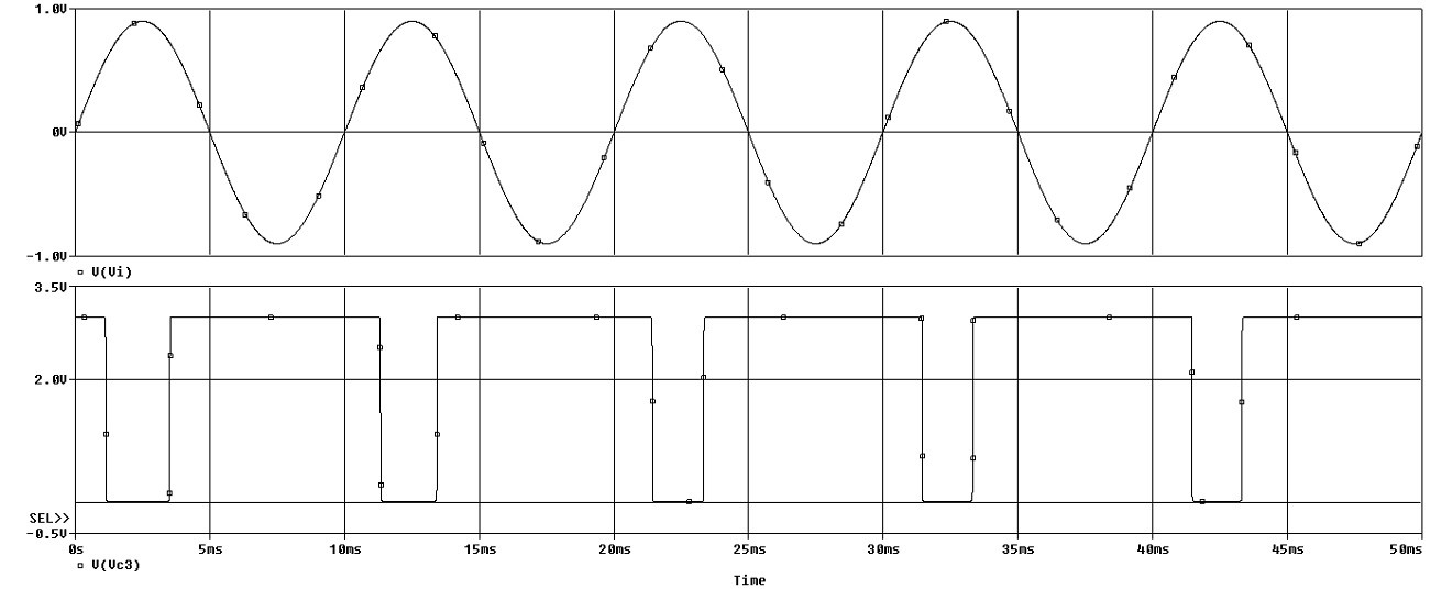
Simulation show high circuit gain:
![]()
You can see that the output transistor (Q3a and Q3b pair) is still saturated even when the input signal is only 1 V. Thus the minimum input signal is 1 V.
-
Opamp Instrumentation Tool
03/26/2020 at 04:15 • 0 commentsIf you know a bit about electronics than you must have seen non-inverting and inverting operational amplifier circuits. This article shows how versatile simple op-amp voltage follower can be.
You can implement this circuit with transistors if you do not have an access to an operational amplifier IC and wire wrap sockets:
https://www.instructables.com/id/Transistor-Sensor-Amplifier/
https://www.instructables.com/id/Recycled-Transistor-Amplifier/
You can see the circuit working in the videos:
Light Motion Sensor and Light Detector
Touch LED
Infra-red Receiver/Remote Control Tester
Frequency LED 1
Frequency LED 2
In the video you see that op-amp saturation voltage would not allow the LED to turn OFF. The minimum supply voltage must be 4.5 V. However, I used a 6 V power source.
Step 1: Design the Circuit
This circuit does not waste any resistor on feedback. An op-amp with zero resistance feedback does not need capacitors and has a high frequency bandwidth. A high resistor feedback will also limit the circuit applications. However, this circuit can only amplify current source inputs and does not amplify voltage sources.
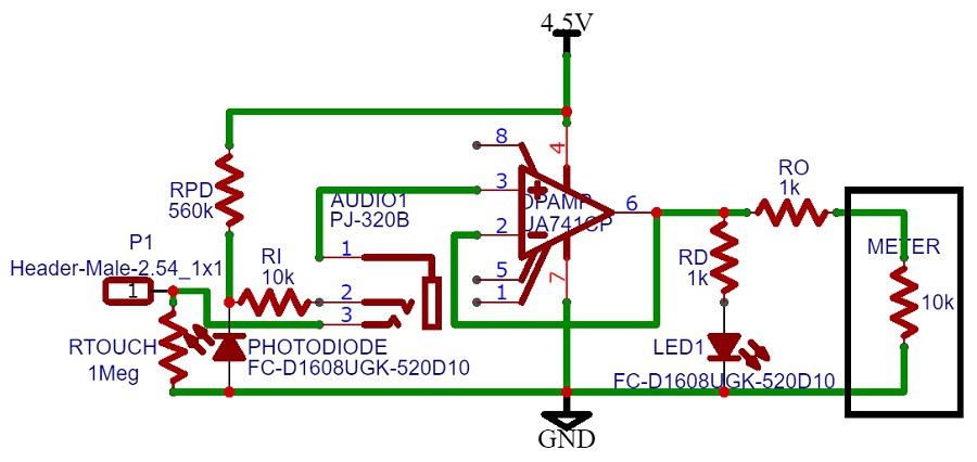
I drawn the circuit in https://easyeda.com online simulation and PCB design software.
![]()
The Ro resistor is used for short circuit protection to prevent op-amp failure. Ri is used to protect the photo-diode from short circuits because op-amp input wire can be connected to power source or the photo-diode circuit output can be accidentally grounded. In both of those instances the photo-diode will fail, unless a 10 kohm resistor is placed in series (shown in the circuit diagram). A similar circuit was implemented for the infra-red receiver. Rtouch resistor is used prevent op-amp saturation due to disconnected inputs for the touch sensor. I connected to oscillator directly to the op-amp input. Than means that negative voltage was entering the op-amp.
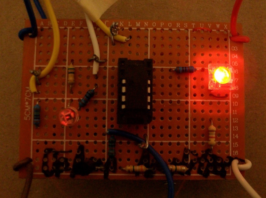
Step 2: Make the Circuit
I used the well known LM741, 8 pin op-amp. However, I did not have an 8 pin wire wrap socket in stock. I used wire wrap tool and a bit of soldering. The black transistor looking component at the bottom is actually an infra-red photo-diode. The normal light photo-diode is on the right of the circuit.
![]()
The yellow wire with a masking tape is connected to op-amp positive input terminal. The white wire is connected photo sensor circuit output. The blue wire at the bottom of the photo is connected to infra-red sensor circuit output. The blue wire at the top left corner was connected to signal generator and the other end to op-amp input (the yellow wire with masking tape). The yellow wire is touch sensor circuit output. You might not need to bias the op-amp input wit the Rtouch 1 Megohm resistor if the LED is OFF. I tried touching with one finger and two fingers (the other finger connected to power supply). The circuit worked with one finger when Rtouch was disconnected.
 tlalexander
 Curt White
 Daniel Zilinec
 Kimio Kosaka
 alessandro verdiesen
 Mile
Mile Sridhar Rajagopal
 Peter
Peter Georgi Angelov
 typematrix
 Steve
Steve Ahmed Azouz
 Vladimir
 Electroniclovers123
 Paulo Kiefe