Close
0%
0%

Camera Control Tablet

RPi-based cyberdeck tablet with a 900mhz WiFi HaLow radio built in

maxmax
Similar projects worth following
0 followers

This project is a Raspberry Pi CM4-based, portable, touchscreen computer for remotely controlling settings on modern cinema cameras. It utilizes 900mhz HaLow communication for wireless bridging, connected to the Ethernet port of whatever camera is in use. The goal is for it to be robust, slick, and professional-looking.

  • V1 - We have liftoff

    max05/10/2024 at 00:33 0 comments

    First entry.

    The goal of this project is to create a small (ish) tablet-style computer for the remote control of cinema camera systems on set. All modern cinema cameras include a web interface of some sort, the main reason we don't rely on these on set is because WiFi systems are not reliable enough. There is just too much interference in the 2.4ghz (and even 5ghz) spectrum on set to get a reliable connection more than a few feet away from the camera. Many attempts have been made to rectify this - stronger antennas, external routers, etc., but none of them have worked any better for me.

    But then I discovered the BitBox, which operates in the 900mhz spectrum instead. While I couldn't afford to pick up one of those lovely systems, it sent me down a rabbit hole of research about 900mhz networking, ultimately landing on the WiFi HaLow protocol. This is a standardized protocol for bridging internet connections over a 900mhz bridge, making them pretty much impervious to interference and increasing range by a ton. The one drawback is lower bandwidth, but camera control is practically nothing, data-wise. It should be perfect.

    I found another camera person making DIY camera control boxes, and from there found the Loocam Bridge kit. This is a $60 plug and play kit for bridging Ethernet connections over 900mhz. It works completely seamlessly, without any setup needed. Kind of mind-blowing.

    My first test was with a SmallHD monitor with a camera control license, and it worked so much better than over wifi that I almost just stopped there - but I really wanted a dedicated device for camera control, rather than running it through my monitor, so I set to work building this little guy. I got it up and running in time for my most recent job, albeit just barely. Work absolutely continued while on set, but it was functioning! The DP called to flip the camera sensor for low-mode, and I was able to do it from my box without needing to reattach the viewfinder.

    Some photos of the current state of things:

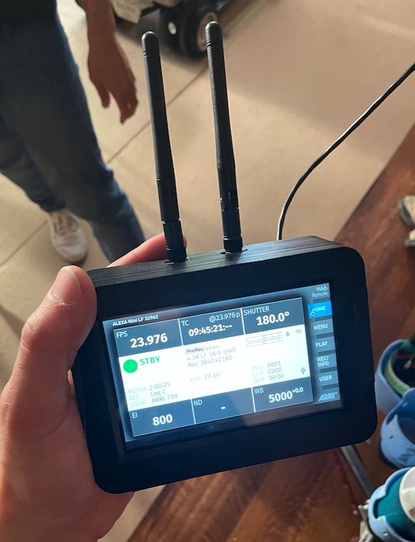
    Front of the box, featuring the touchscreen
    Front of the box, featuring the touchscreen & ARRI web interface
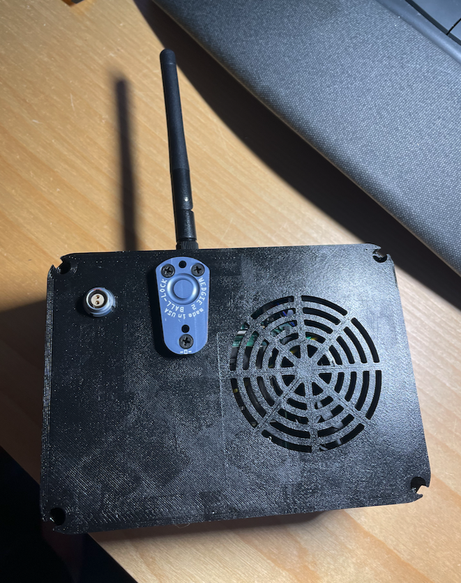
    Rear of the box, with 2-pin Lemo for power (9-32v), Wedgie2 for mounting, and fan cutout
    Rear of the box, with 2-pin Lemo for power (9-32v), Wedgie2 for mounting, and fan cutout
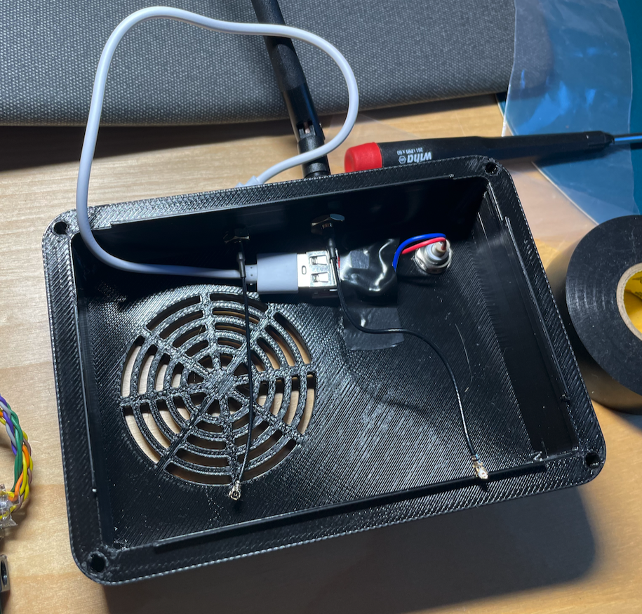
    Inside the rear cover, feat. the antenna connectors for wifi (currently too short) and 900mhz, plus the power regulation
    Inside the rear cover, feat. the antenna connectors for wifi (currently too short) and 900mhz, plus the power regulation
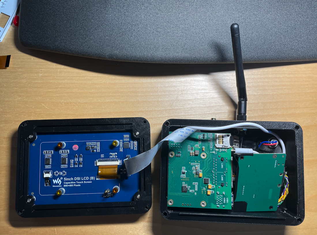
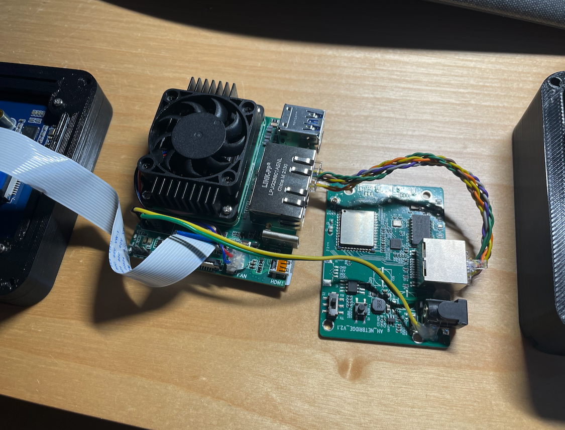
    The very tight pack of all three boards. Currently only the screen is actually mounted, the rest are just tight...
    The very tight pack of all three boards. Currently only the screen is actually mounted, the rest are just tight...
    Power and data for the 900mhz board
    Power and data for the 900mhz board

    I was reluctant to permanently modify the 900mhz board (a Netbridge 2.1 board from Loocam) until I was sure this would work, so at the moment I've just soldered the power and ground lines onto the sides of the barrel jack. It should be able to pop back into its original housing without issue, though now that it *is* working here, I doubt I will ever do that. Perhaps I will remove the barrel jack entirely now for space savings.

    Challenges that I had to overcome to get to this point:

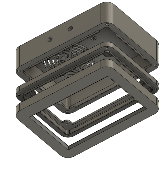
    • Designing the case. I didn't want to use the adhesive backing on the LCD, in case I needed to redesign the case later on down the road. I also wanted to essentially overmold the edges of the LCD to protect it from bumps. I landed on a 3-layer design, which is probably over complicated, but oh well. The LCD is screwed into the middle "frame" part, then covered with the front panel. The pi and 900mhz board go into the rear case, then the ribbon connects the two halves. I added some fins and slots on all four sides to help align the parts, and there's an M3x40 screw in each corner to bind the whole thing shut...but at the moment it's just gaff taped closed so I can easily access the insides for further tinkering.
    The case, exploded
    The case, exploded
    • Getting the touchscreen working. I selected a Waveshare LCD module (5in DSI LCD B), but first attempted this with a BTT Pi TFT which I just could not get working. The Waveshare worked fine once I figured out that I needed...
    Read more »

View project log

Enjoy this project?

Share

Discussions

Similar Projects

Does this project spark your interest?

Become a member to follow this project and never miss any updates