 UTSOURCE
Step 1: Things You Need
- Arduino UNO
- Photo Interrupter Module
- Breadboard
- Connecting Wires
Step 2: Schematics
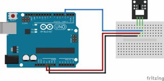
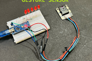
Connect the power line (middle) and ground (left) to +5V and GND respectively. Connect signal (S) to pin 3 on the Arduino.
KY-010 - Arduino
- (left) - GND
middle - +5V
S (right) - Pin 3
Step 3: Code
Please copy the following code and upload it to your arduino Board :
int Led = 13; // define LED pin
int buttonpin = 3; // define photo interrupter signal pin
int val; //define a numeric variable
void setup()
{
pinMode(Led, OUTPUT); // LED pin as output
pinMode(buttonpin, INPUT); //photo interrupter pin as input
}
void loop()
{
val=digitalRead(buttonpin); //read the value of the sensor
if(val == HIGH) // turn on LED when sensor is blocked
{
digitalWrite(Led,HIGH);
}
else
{
digitalWrite(Led,LOW);
}
}
Step 4: Testing Photo Interrupter Module
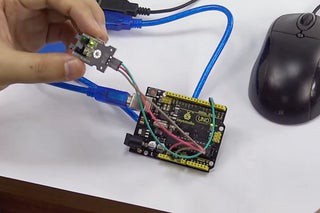
The arduino will light up the LED (pin 13) on the Arduino when there's an object blocking the beam of light between the sensor's gap.

 Hulk
Hulk
 ElectroBoy