This project was developed in partnership with Robô Lúdico Schooland JLCPCB Factory that offers 5 free PCBs of Arduino Compatible Board.
In commercial establishments, it is very common to use panels with LED arrays to display some information such as Product prices, welcome messages to customers, among other messages.
These matrices are very useful, as they are larger than LCD displays, Oled because they can be viewed from a distance.
So in this article, we will learn how to control this matrix through a mobile application that will be developed in MIT APP Inventor.
With this application, it will be possible to send personalized texts to be displayed in this matrix.
In this project, we will use 4 LED arrays connected in series to compose our panel.
You can use multiple arrays in this project. To do this, just make some changes to the code.
Therefore, through this article you will learn:
1 - Perform the assembly of the circuit on the protoboard;
2 - Communication of the Arduino with the Bluetooth module;
3 - Develop the mobile application using the APP Inventor;
4 - Understand the operation of the led matrix;
5 - Understand the functioning of the ci used to control this matrix.
Now, we will start the complete presentation of the project development Controlling a panel of led arrays through a mobile application.
DEVELOPING THE PROJECT CONTROLLING A LED MATRIX PANEL THROUGH A MOBILE APPLICATION
As previously mentioned, we developed firmware to control the LED arrays and write texts on them.
This text will be sent through an application installed on a cell phone and sent through the cell phone's Bluetooth communication with the Arduino Uno board.
You will receive this text and process it to be printed on the LED arrays.
Therefore, first, the firmware for the Arduino will be developed, and then the mobile application for the cell phone.
The project circuit with the LED matrix is shown in Figure 1.
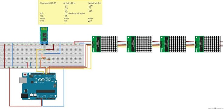
Figure 1 - Schematic circuit with the Bluetooth module connections and the LED arrays to the Arduino Uno.
In this circuit the Bluetooth module is powered with a voltage of 5 V at the VCC terminal, however, its logic level is 3.3 V.
For this reason, the RX terminal of the Bluetooth module requires a resistive divider to attenuate the 5V voltage, which comes from the Arduino Nano.
If you do not use the resistive divider, the module will burn over time.
To calculate the resistive divisor, equation 1 is used:
Vout = ( R2 / R1 + R2) x Vin
3.3 = (10.000 / R1 + 10000) x 5
3.3 R1 + 33000 = 50000
3.3 R1 = 50000 – 33000
3.3 R1 = 17.000
R1 = 17.000 / 3.3
R1 = 5 KΩ
Therefore, we will use a 5k resistor and a 10k resistor in our resistive divider with the assembled circuit.
Now, let's go to Arduino programming.
The Matrix Structure of 8x8 LEDs
The led matrix is a component that has 64 interconnected leds and distributed in 8 rows and 8 columns. The LED matrix is presented below.
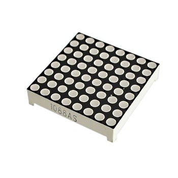
Figure 2 - The LED Matrix.
It is made in order to facilitate the individual activation of each led.
So instead of 65 pins, it has only 16 pins.
This solution is achieved by interconnecting the LEDs by rows and columns. The LEDs of each column have the anodes interconnected and the LEDs of each line have the cathodes interconnected. But this configuration can change depending on the type of matrix used.
Currently, there are two types of the matrix on the market: common anode and common cathode.
In figure 3 we have the scheme of the two possible connections in a led matrix.

Figure 3 - Possible connections in a led matrix.
The figure on the left is a common cathode matrix and the other is a common anode.
Performing the matrix drive in this way would use many uC pins, so it is not very feasible.
That way we will use a ready-made module that has a Ci Max 7219. It is dedicated to controlling this matrix using only 3 pins: Din, CS, CLK.
Using this ci we can control the 4 LED arrays using only 3 pins of the Arduino...
Read more »
 Sagar 001
 Jayahari J