 kelvinA
- Me In The Past, looking at the CAD a day or two before ordering it:
- I've trimmed as much as I can. It's unlikely that this heatblock could use any less material, and if it's possible, I'd like to see it
- Me Today:
- Me In The Past, what lies!
Just like how the iPhone rumour mill will switch right to the iPhone N+1 leaks on the launch of the iPhone N, I've decided that I am indeed going to spend "15 minutes" to implement the tweaks I've had in my mind. The urge to do so stemmed from the fact that I spent 90 minutes this morning switching out the partially melted hotend holder with a fresh one (still in PLA unfortunately) because the "chamber fan" didn't turn on like it was supposed to when I did a PID of the Coaxial8or.
Let's rewind a bit.
Heating tests
So the heating test with the CHC Pro was simple enough actually. I first heated it up just so that I could remove the other components currently attached to it and then attach it to the Coaxial8or. Surprisingly, not a lot of torque is applied through to the CHC Pro when tightening the nozzle, suggesting that I might still have somewhat easier nozzle changes than a usual hotend setup.
Then I found out that I can't actually set the temperature of the coaxial8or, which was on Heater1 (instead of Heater0 for the machined coaxial hotend back in Jan/Feb). I immediately decided to pivot and use the provisions coded into Marlin for the chamber heater. This is what I've done inside the pins.h of the Octopus:
//
// Heaters / Fans
//
#define HEATER_CHAMBER_PIN   PA1
#define HEATER_0_PIN         PA2   // Heater0
#define HEATER_BED_PIN       PA3   // Hotbed (default PA1)
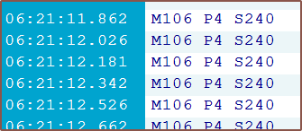
I also tried (and failed) to set an auto chamber fan. The chamber fan doesn't come on at all, and there's a separate CHAMBER_FAN thing that, when configured to the below, turns on if the set temperature is >=10 degrees and turns off immediately otherwise. It also causes spam in the serial port.
#define CHAMBER_FAN
#if ENABLED(CHAMBER_FAN)
    #define CHAMBER_FAN_INDEX     4
    #define CHAMBER_FAN_MODE      0
Long story short, the MPC autotune of the CHC Pro was eventless, but the PID tune of the Coaxial8or left the hotend assembly wobbly and the M3x45mm bolts hot to the touch.
As for temp stats:
- C8or 160C and CHC unpowered = CHC at 131C
- C8or 160C and CHC 210C = CHC running at 50% power and temperature oscillations for the CHC are +0.0 and -0.2 degrees.
- CHC can also easily reach 210C when the C8or is unpowered, suggesting that I'm not losing too much thermal energy through the connection at the moment.
Part cooling
Also to mention, the part cooling fan does seem to direct air closer to straight-down. I'm hoping to make a duct that can disperse this airflow (instead of usual designs that try and force as much as possible through the nozzle) as I believe that it would better cool the part. My hypothesis is that, since the nozzle usually moves away from the hot material relatively fast, focusing all the cooling on that one location isn't a good idea. Additionally, from doing those thermal simulations for the unibody coaxial hotend, I've found out that a 2x increase in air speed doesn't translate much into the amount of temperature reduction of a heated body.
Heatsink cooling
Before I swapped the hotend holder, I wanted to see if the cooling would've actually been adequate to keep temps under control. I enabled the CHAMBER_FAN and set the temp to 160C for 15 minutes (basically where I got the "temp stats" seen further up in the log) and the mounting bolts were cool so things seemed good enough for me.
Swapping the hotend holder
So the warping wasn't actually that bad, but I only found out once I had actually taken the holder off. Cue the next 60 minutes of me essentially dissassembling and reassembling everything, because I still need to see though the couplers to know what resultant force vectors to apply to get the heatsinks to slide into the couplers.
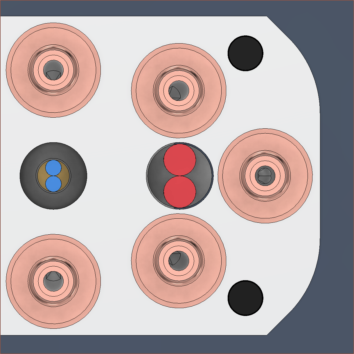
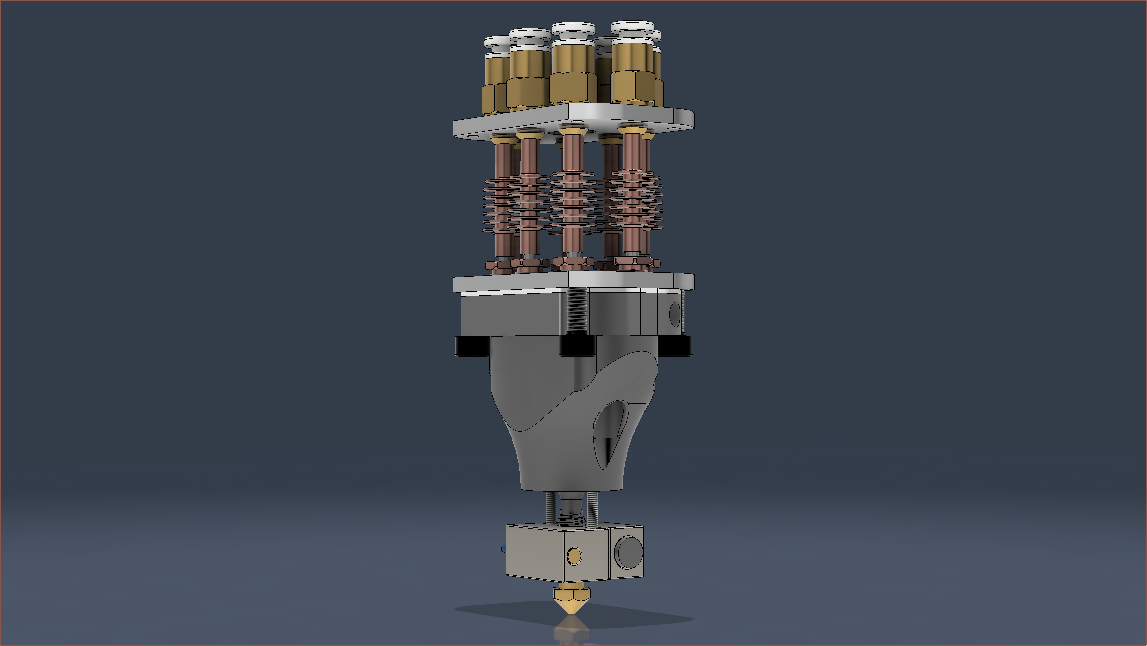
The first revision of the Coaxial8or
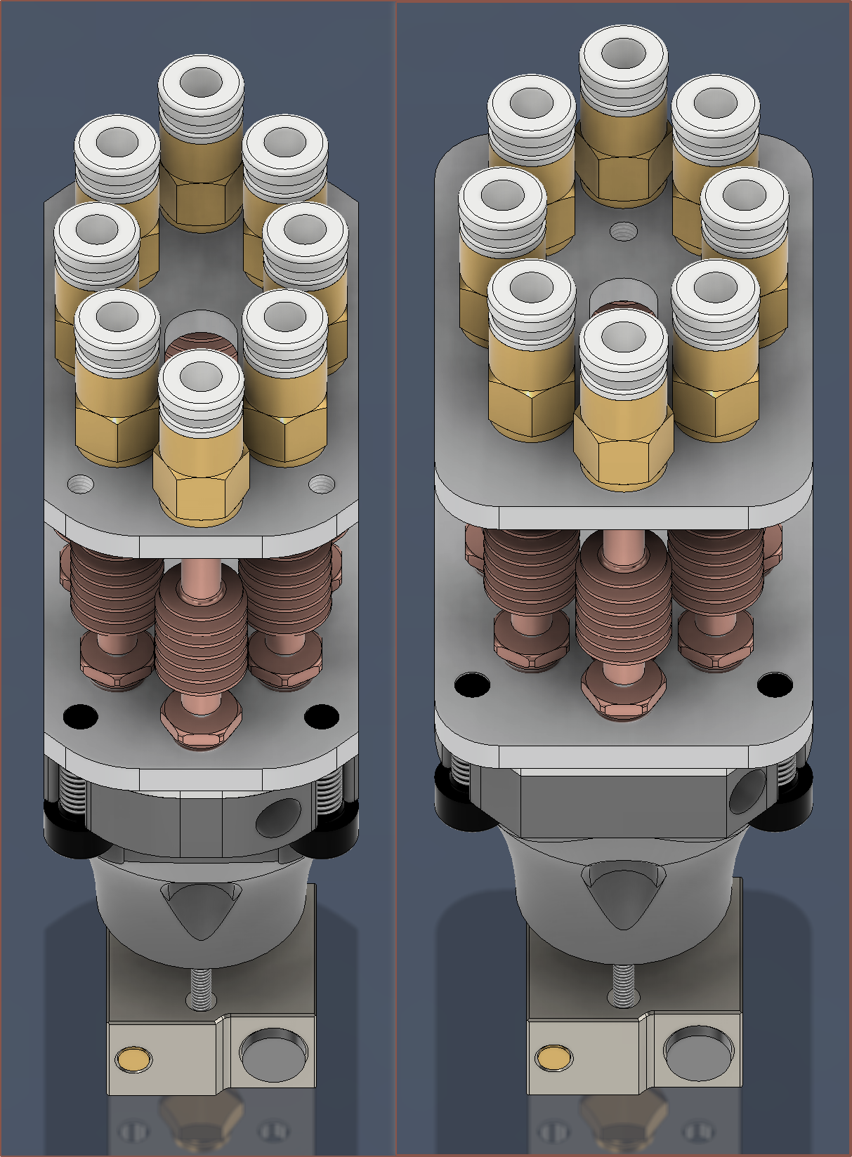
When I finally finished with the CAD, I was thinking that it looked quite slim considering that the dimensions have only changed from 35*49mm to 30*50mm (notice the divisibility of 7 and 10 respectively as it's one of those nice round numbers that nobody but the engineer (aka myself) would care about). It's only when I got this screen snip that I could certified say that it was notably thinner. At the same time though, the minimum distance between inputs has actually increased (to 11.3mm), meaning that I could use 10mm diameter couplers if desired.
The thinness is important, since I'm trying as hard as possible to preserve a 300*300*300mm print area on my CR600s. Without modifications, a CR-10 or Ender3 would presumably lose only 9mm from the Y axis with this hotend compared to the default hotend (which is 12mm thick).
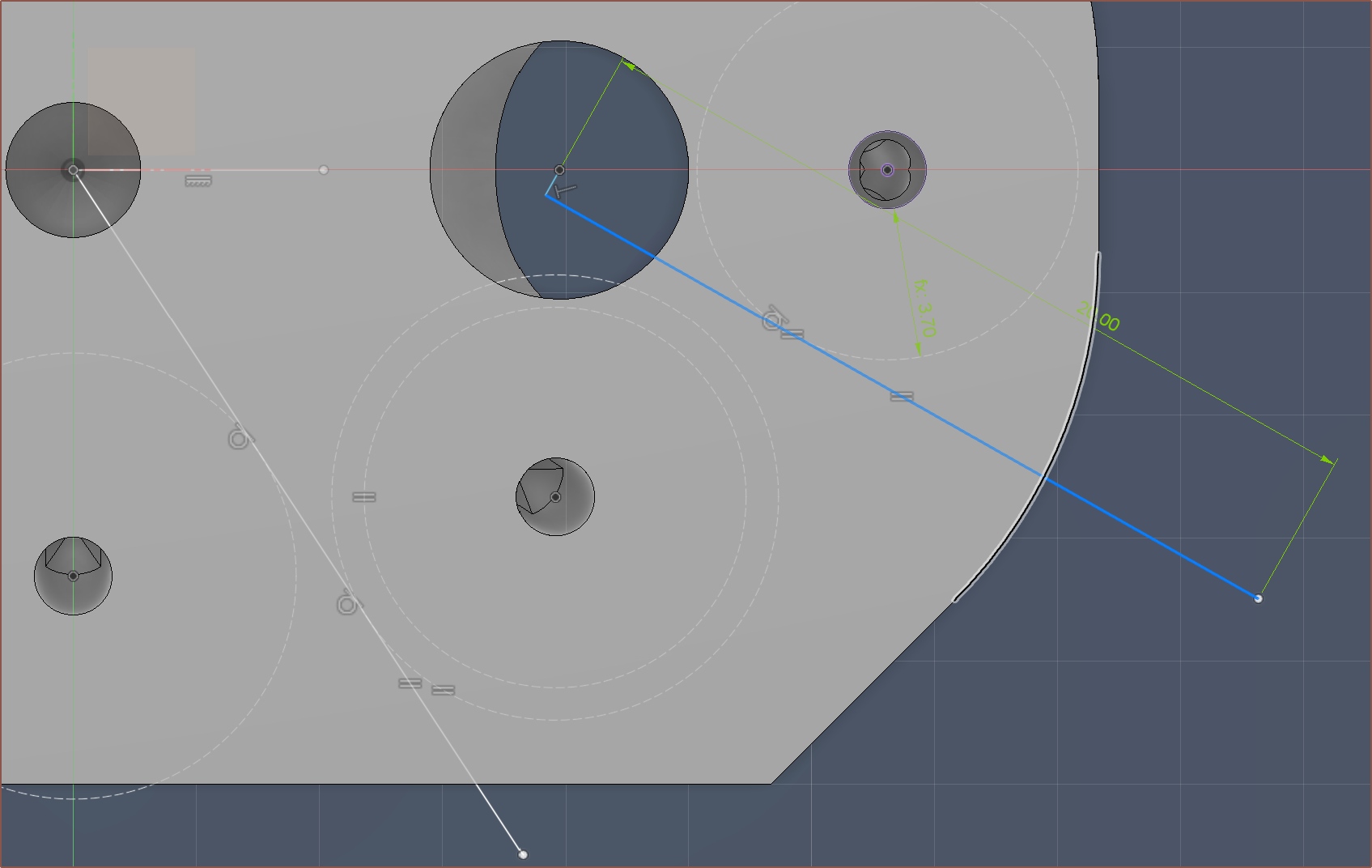
I thought it was game over when I couldn't find space for the M4 clamp plates, but after a break, I quickly realised that I could just delete a 135-degree constraint so that I could move the grub screw hole out of the way.
I've also now gone with 4 M3's on the outside for the coupler plate, and that's so that I can print 2 halves of a hotend holder and screw them on with an allen key after aligning the heatsinks to the couplers.
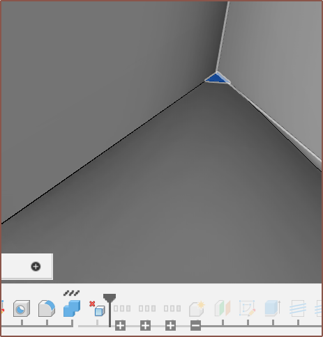
I've deleted all the really small triangles that I had made in the negative mould geometry:
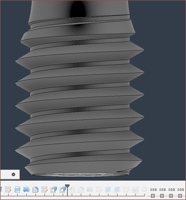
I've sharpened the printed M6 thread since the thread that was printed seemed a bit lacking. Ideally, I'd actually make a custom thread that has 45 degree angles instead of the 32 degrees seen here for a traditional M6:
I also want to mention that I got rid of the legacy Unibody Coaxial Hotend geometry (a.k.a. the heatsink part) from the file.
Oh, right, speaking of heatsinks, I've made sure that there's enough space so that they can be taken out without having to unscew any heatsinks. In the currently-printed design, the heatsink covers the heater cartridges by 1 entire millimetre, stopping it from being taken out.
Conclusions
So there you have it, a new design that actually took 3.5 hours to generate, not "15 minutes" as I claimed.
I was just worried that, if I needed to increase the spacing of the coaxialiser center, I would essentially have to be trying to do a respin of everything just because of a single change. Despite me worrying about it all week, I still haven't increased the spacing from 0.95mm, as I want to test out the current one before I increase it. I'm just somewhat glad that, if I desire to get the Coaxial8or respun, it's not a ClickOnce change. Still though, I doubt I would've actually needed a physical model to apply the changes that I've done today.
Trivia
I like how I finished the new design on the 7th save, resulting in "Coaxial8or r1 v8":

As you may also notice, I haven't added a fillet to the main body of the heatblock, and that's because everything was already so smooth and flowing that I thought that the sharp edge in the surface would make it look sleeker and less bottle-like, similar to the surface designs on cars.
[Mar 22]
On the day I ordered the current Coaxial8or print, and today, I was thinking about Mark Rober, a youtuber, talking about what he coins the "Super Mario Effect" (and mentioned by Forbes). The main takeaway is that, with no penalties or drawbacks, participants tried nearly 2.5x more attempts and got a 16% better result.
I found that interesting, but moreso was the flipped around argument; even with a penalty and, as a result, attempting 2.5X less, the other participants were only 16% away from a more optimal result. This gave me the confidence to finally order the hotend, knowing that "well I'm probably within 16% of the optimal solution".
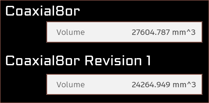
Today, I was able to get the depth down to 29mm and mass to 63.5g. To sound a bit like Apple, the resulting design is a 17.4% reduction in depth and a 14.7% reduction in volume from the current "r0" design. I've broken the sub 24,000mm^3 barrier and now the heatblock sits at 23,555mm^3. It also means that I've now cut the Y offset by a round 3 milllimetres.
Discussions
Become a Hackaday.io Member
Create an account to leave a comment. Already have an account? Log In.