 Dimitar
Hey,
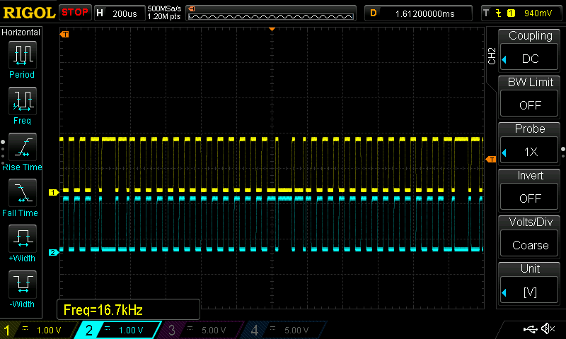
We have seen from my previous log what the theory of operation should be. Now we will take a caliper apart and see that signals are actually generated and take some measurements.

I took this snapshot with my scope. We can see that the pattern repeats every 1.98ms and one pulse takes 60uS
From first glance we could assume that this is PWM and in a sense it is, but its not the one we have seen while driving LEDs for example. Lets look the steps one by one and describe them.

1. All of the 60uS are HIGH, we have only one step like this in the beginning.
2. 15uS HIGH, then 15uS LOW and the rest 30uS are HIGH, this step repeats twice .
3. First half i.e. 30uS is LOW and the rest is HIGH, this repeats 13 times.
4. 45uS is LOW and only 15 HIGH, only once.
5. All 60uS are spent LOW, once in the middle.
6. 15uS LOW 15us HIGH and the rest 30uS are low, this repeats twice.
7. 30uS HIGH 30uS LOW, this repeats 12 times.
8. 45uS HIGH and 15uS LOW just once in the end of the pattern.
Of course we have a complimentary signal that is the opposite.
I don't have any ideas how I could 4 signals like this shifted 90 deg of each other using the timers on the STM32F103, so the best approach for me would be to do it with bit banging since all of the pins are connected to one port.
Next step is to reproduce this pattern on my own hardware!
Cheers,
M.
Discussions
Become a Hackaday.io Member
Create an account to leave a comment. Already have an account? Log In.