Dimitar
-
Design
02/10/2024 at 19:56 • 0 comments![]()
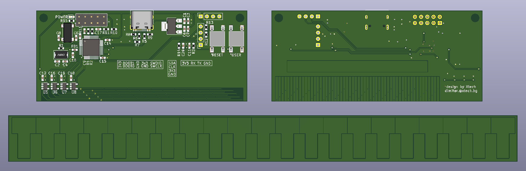
From the image above you can see the front, the back and the t-scale for my caliper. Bellow I will list a few things I considered while making this design.
- I chose the STM32F103 used in the blue pill because it is capable, cheap and schematic is available. People love it. Hopefully I could get help with the code if needed.
- I made the MCU board with 2 layer PCB, the t-scale is single layer board. I did not want to make the paths and vias small. Since I knew the proportions I decided to make everything larger than the one you will find in a store both caliper. All of this will make the board cheap to manufacture. A set is $2.25 with shipment from China.
- It is populate on one side and the components are fairly large. I decide not to get a stencil. The component count is small and the size of the them is relatively large. I think I will get away with manually applying the solder paste. I don't get paid for this projects, so cheap as possible is the name of the game.
- The through hole components are located on the top side of the board, so they don't interfere with the scale moving. Two holes are present for mounting.
- The 2x5 pin horizontal connector is for boot select, power and debugging.
- The 4 pin horizontal connector is an UART with power. If someone wants to implement a text based protocol for communication.
- The 4 pin vertical connector is made for a OLED 0.91" display (i2c). It should cover the central part of the PCB.
- USB 2.0 full speed with USB C connector for good measure.
- Two buttons, reset and a user button.
- Last but not least a power indicating LED. I always regret not putting a LED that indicates if my board is power or not.
Here are some links: schematics, BOM, footprints, gerbers.
-
Research
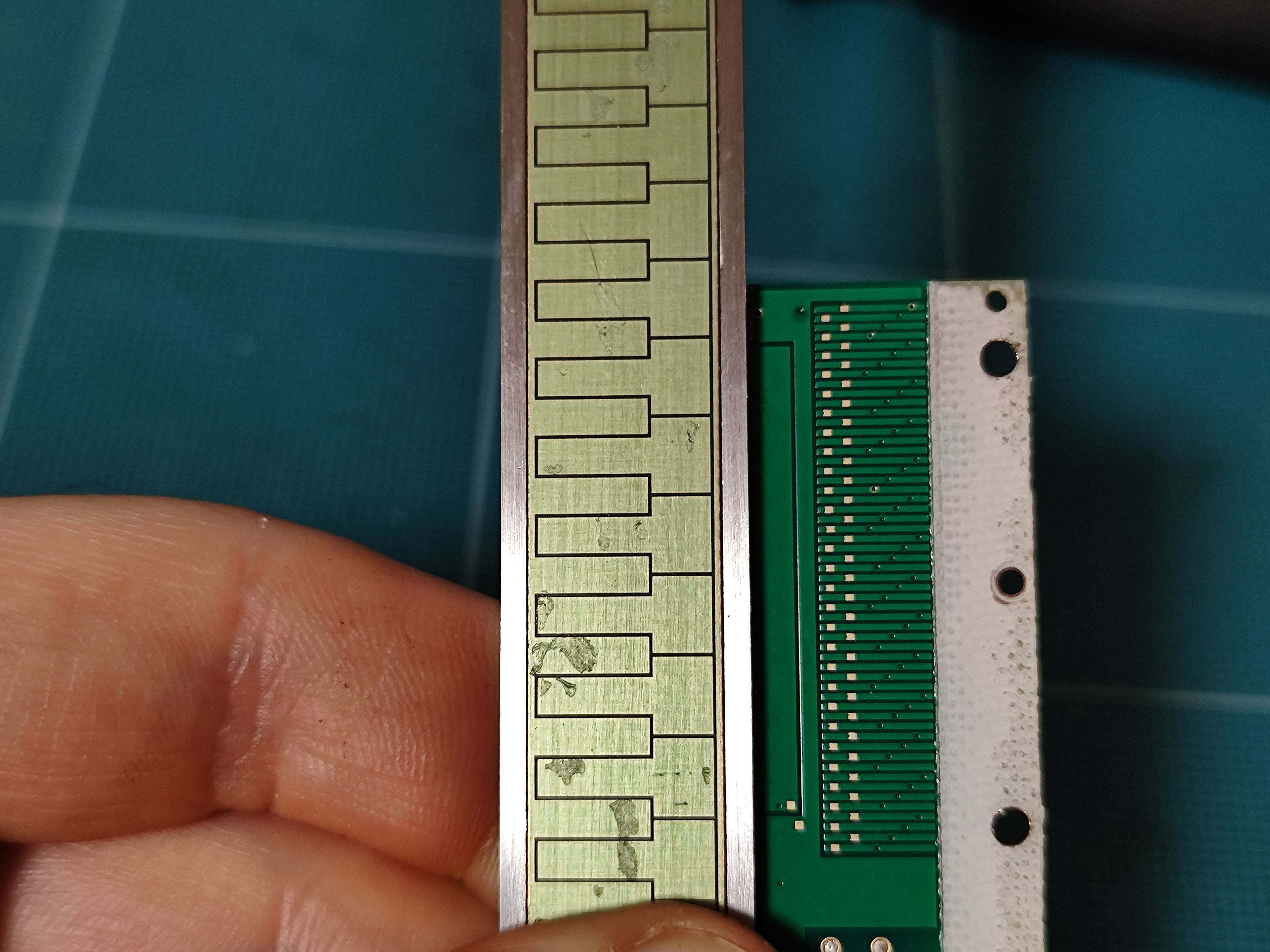
02/10/2024 at 18:29 • 1 commentI was think that I need get my hands on a a caliper first and disassemble it. To be honest I did not get any super interesting information out of that. I just ruined perfectly good caliper. The t-scale PCB is 0.5mm thick and has copper only on one side with very thin solder mask. It was covered by a sticker. The PCB containing the MCU and the sensor is 2 sided but populate just on one side. The interesting thing about it is that it is machined to fit inside the caliper head. Also the it utilizes COB (Chip on Board). I tried to strip the black epoxy, what I found is the the silica was placed as close as possible to the via of the sensor pad. Later on I recreated that as well on my own design.
![]()
I tried to measure what is the width of the T scale and the electrodes on the MCU PCB, but with no luck. It was hard aligning the two PCBs and also the solder mask did not made it any easier. All I could do is to test for contact with a multimeter.
It wasn't immediately clear to me how the caliper works, so I decided to do some digging
First is a primer about how capacitor sensor work. Capacitive Sensors by L. K. Baxter. When we start running experiments we will go back to this document to be able to understand the variables in play when dealing with cap sensors.
Second is a article from a site called Yardo The biggest gold from it is this beautiful oscilloscope screenshot
![]()
From here we could see that we need to generate 8 PWM signals. We can group 2 together as one is inversion of the other. We could see that those signal generate sin waves with periods shifted 90 degree. Also we see the signal generated by the movement of the caliper.
The next article is the US patent for Capacitive displacement measuring device with t-shaped scale. From this, we can draw two key insights. One is that there were a lot of smart people in 1991 and also this block diagram:
![]()
It will help us later to figure out how to process the signal we measure back from the sensor pad.
So far so good, but we still don't know how to design our T-scale and transition group. We could find that in this article called A High Precision Capacitive Linear Displacement Sensor.
![]()
In this paper they are using two pairs of capacitors S+ S- and C+ C-. The orange shape should be the vertical part of our T-scale. We could clearly see that it should span over S+ C+ and one gap spacing.
Armed with this information I will be making my own footprints for the T-scale and capacitor groups.
DIY Digital Caliper
I design my own digital caliper based on STM32F103 blue pill.