 Arnov Sharma
PCB Design
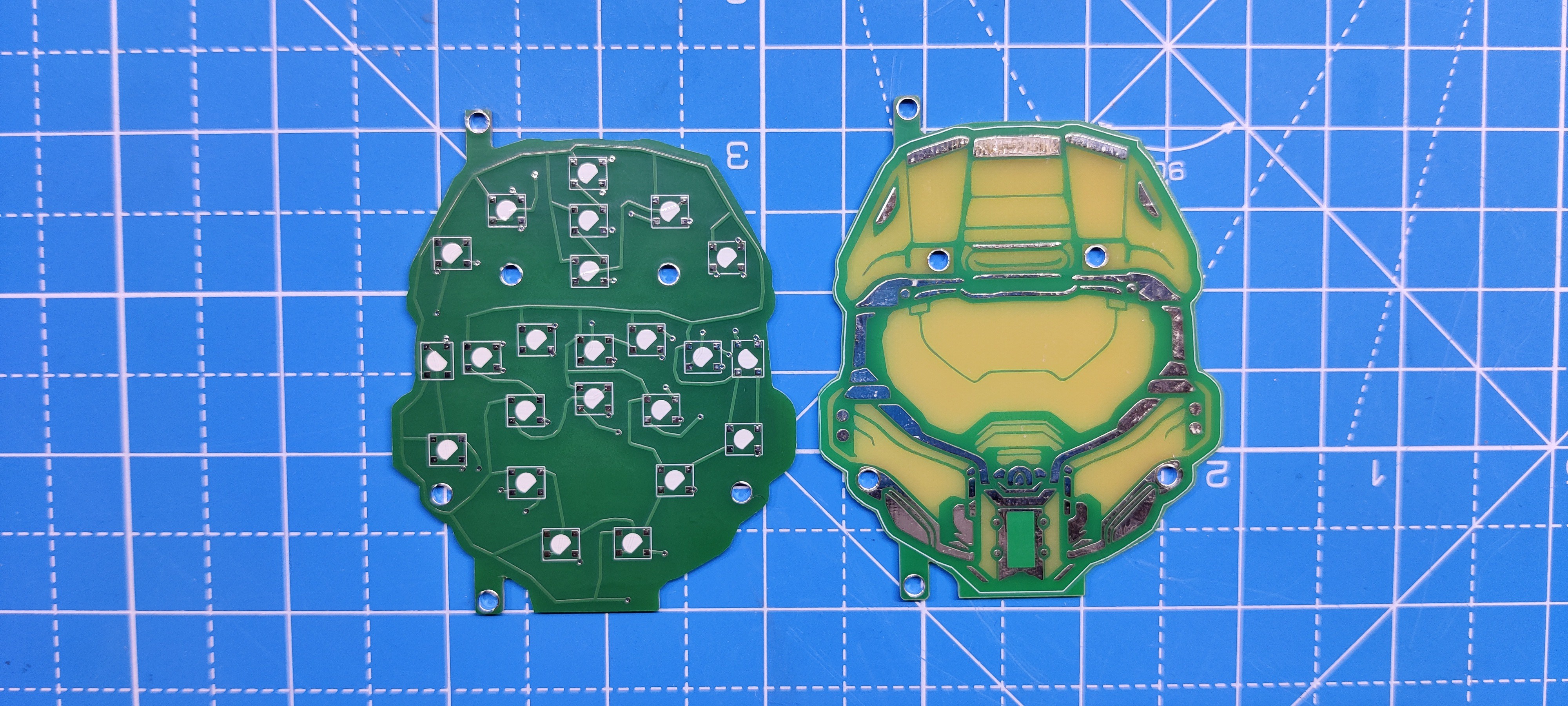
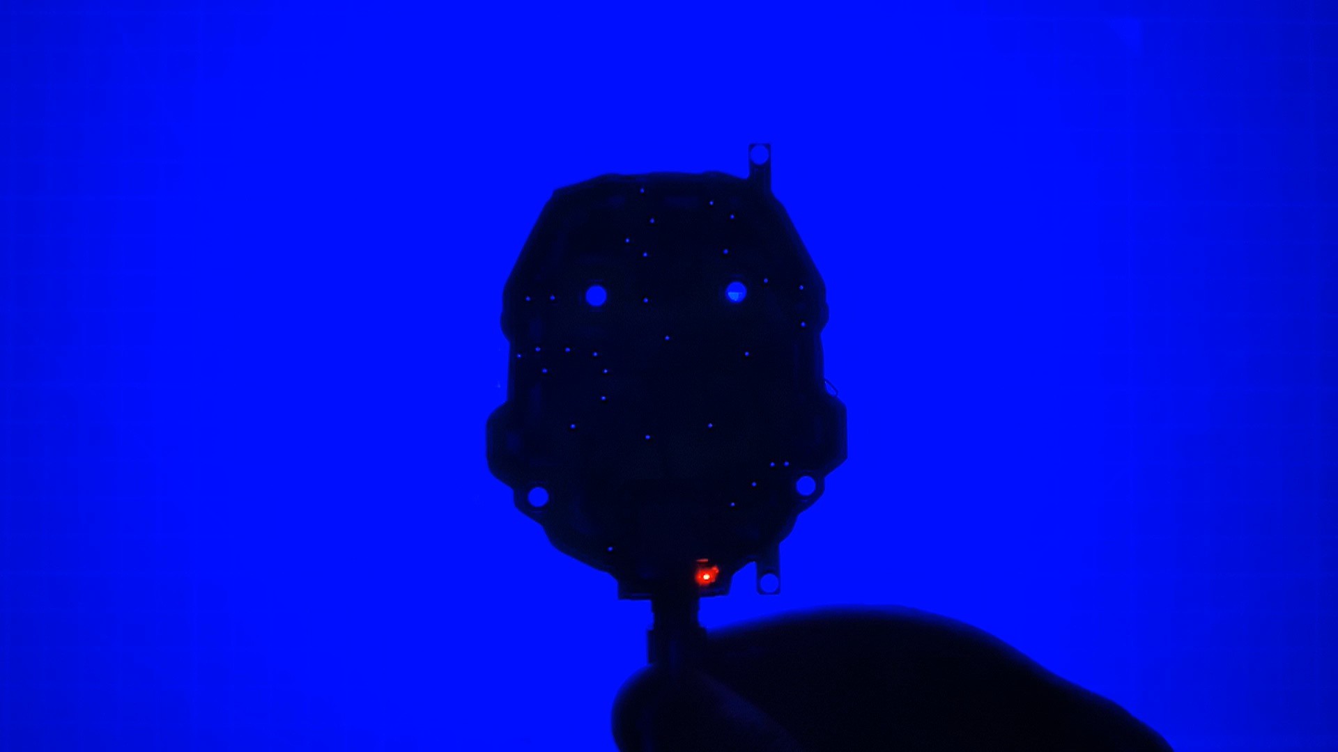
The PCB design for this project was split into two parts: the top layer board, or first board, which is just made up of solder mask opening layers, and a silkscreen that was themed after the helmet of the master chief.
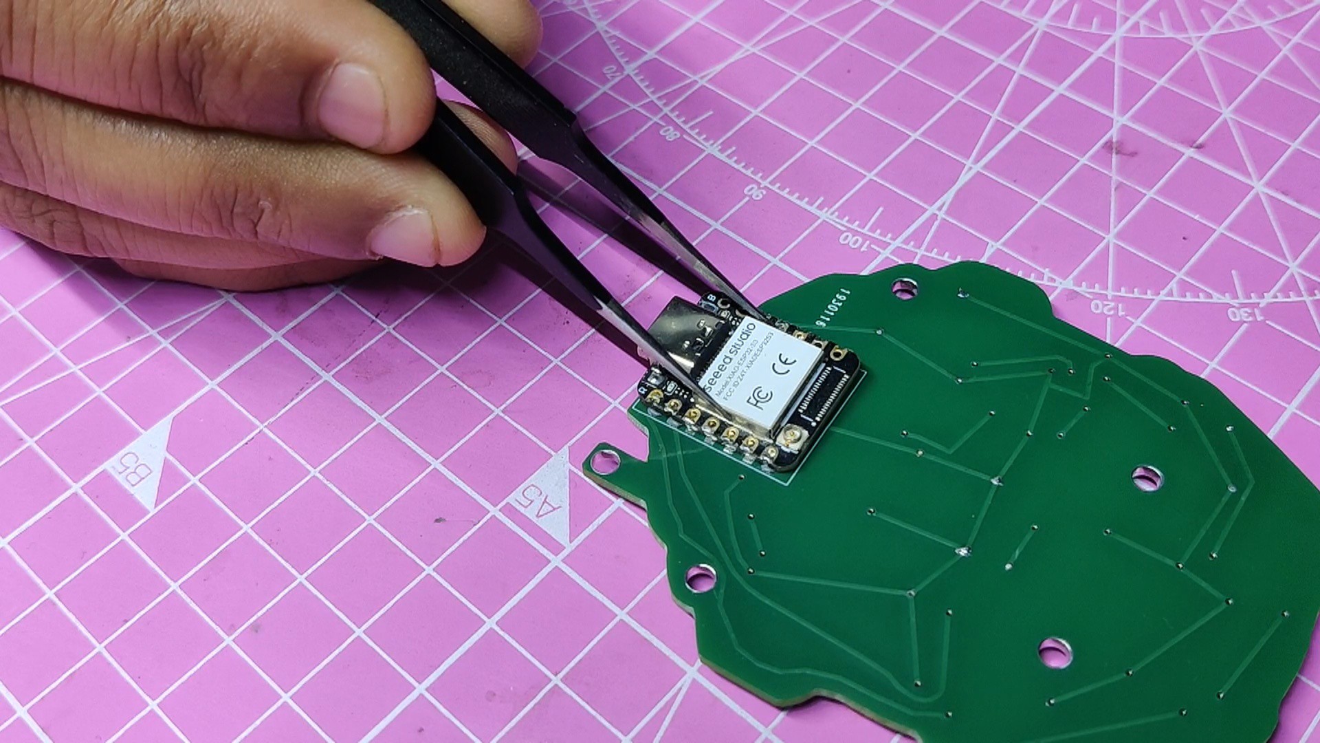
The RGB LEDs and XIAO MCU are positioned on the second, or bottom, board. The RGB LEDs' glow is visible through the top PCB's solder mask opening.
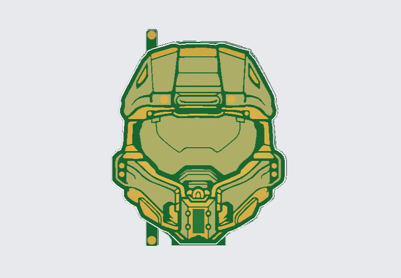
We first looked for a black and white picture of Masterchief's helmet to use for the first layer, and we found one that will work perfectly.
We converted the image into BMP as we're using OrCad Cadence, which only imports logo files as BMP images.
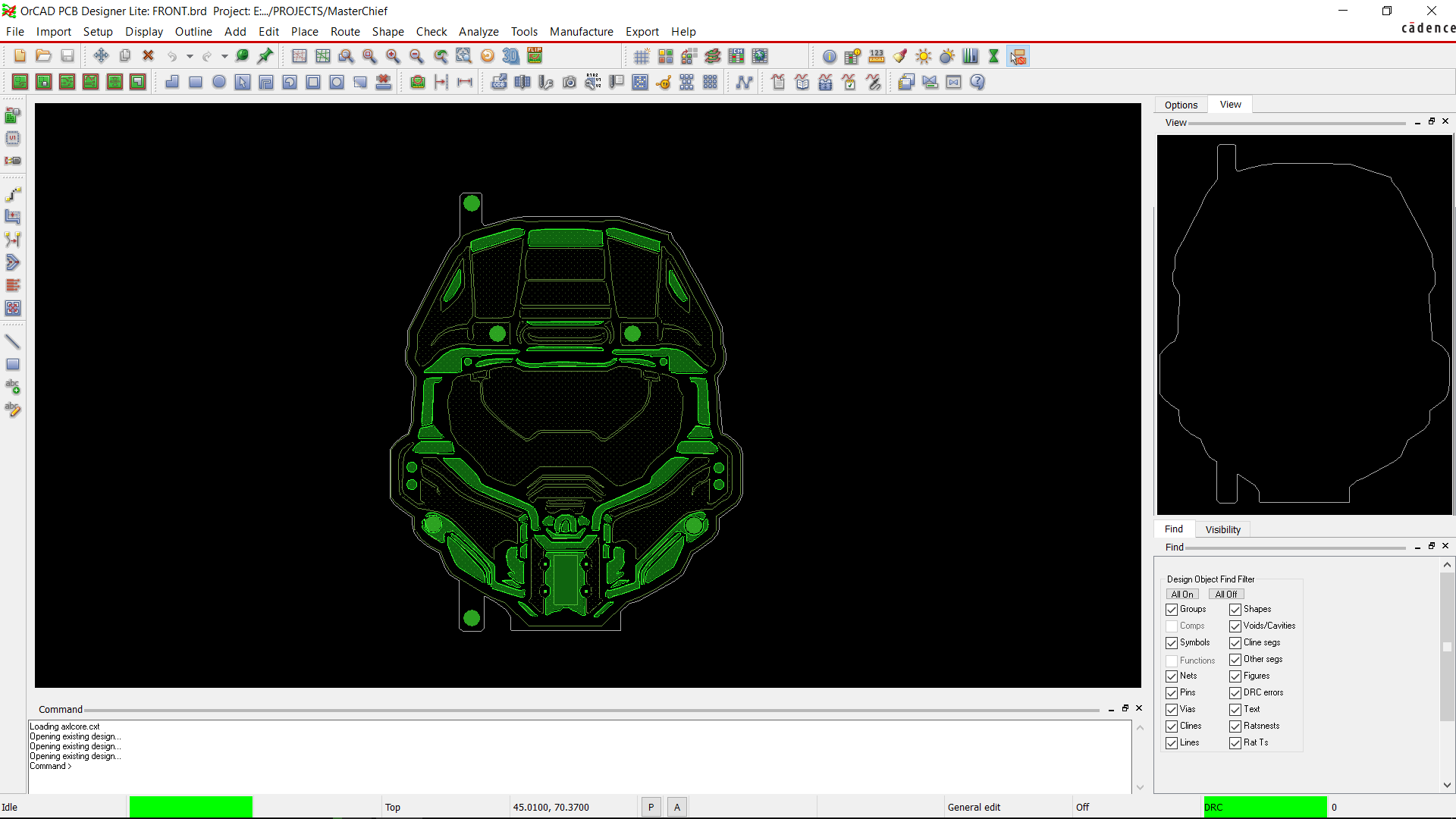
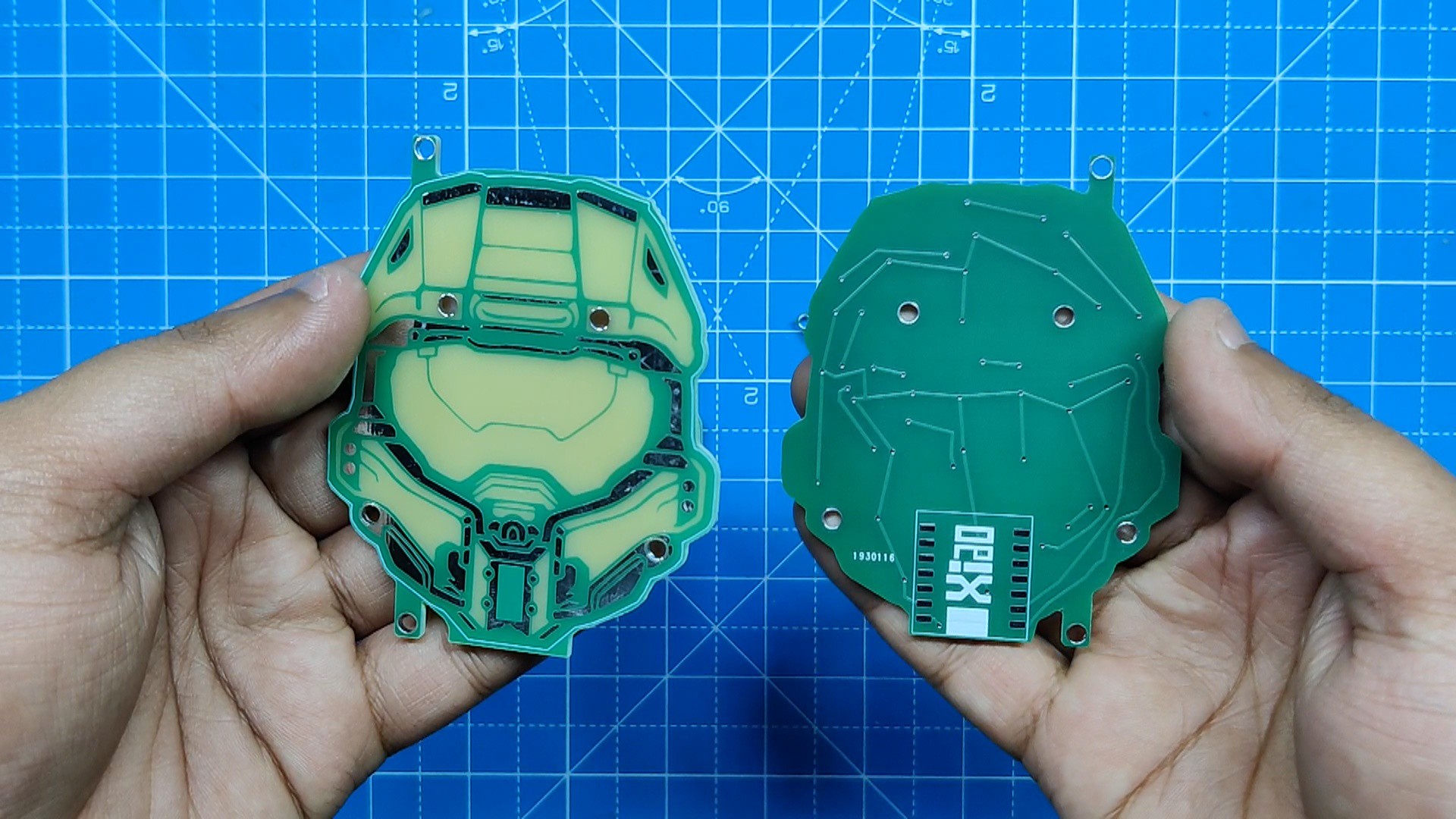
After adding the basic image inside the CAD software, we added a top-etch layer by tracing out the helmet outlines. After that, we add a soldermask opening on top of the etch layer, which exposes the empty FR4 board along with the etch layer.
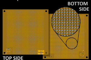
The etch layer, when exposed, will look silver or gold depending on the PCB surface finish, which in our case will be HASL or silver.
We added a soldermask opening on the bottom side as well, so light can easily transfer through the PCB.
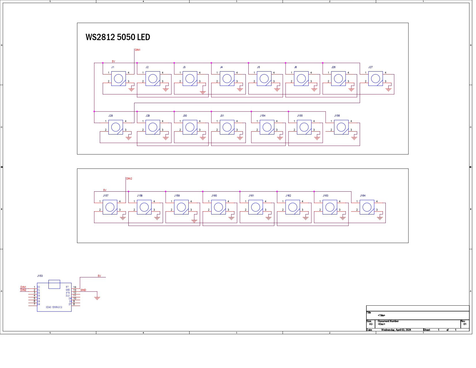
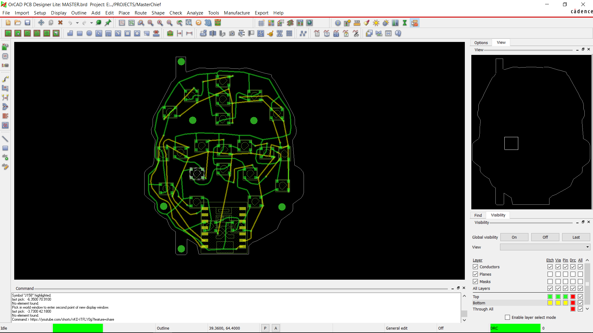
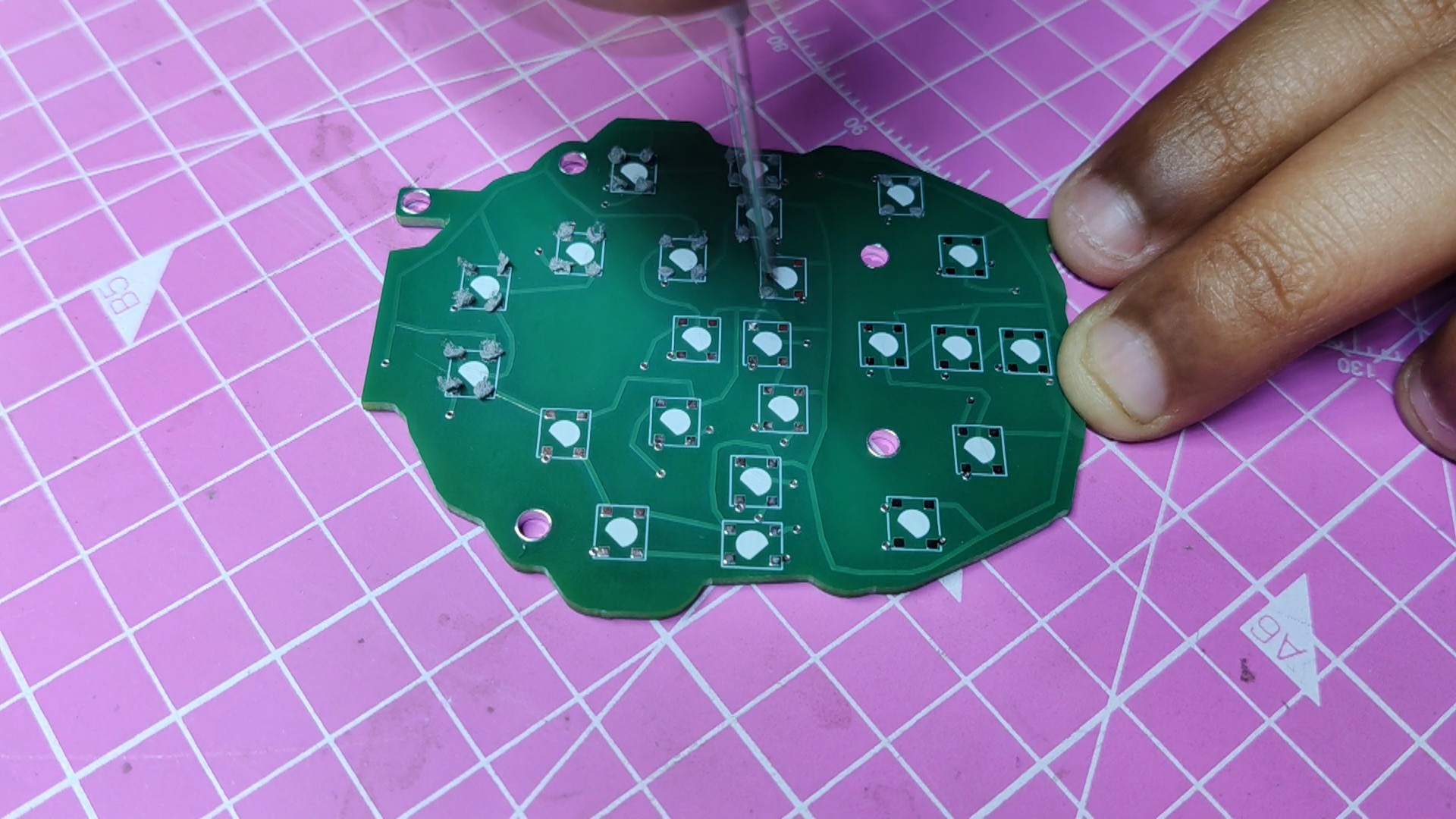
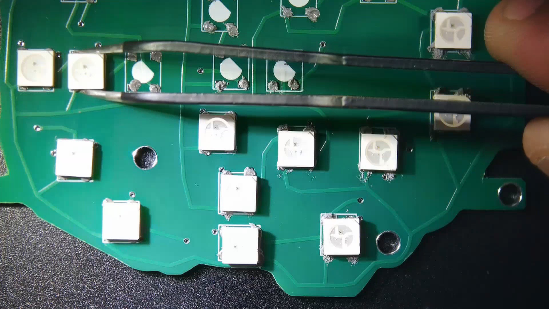
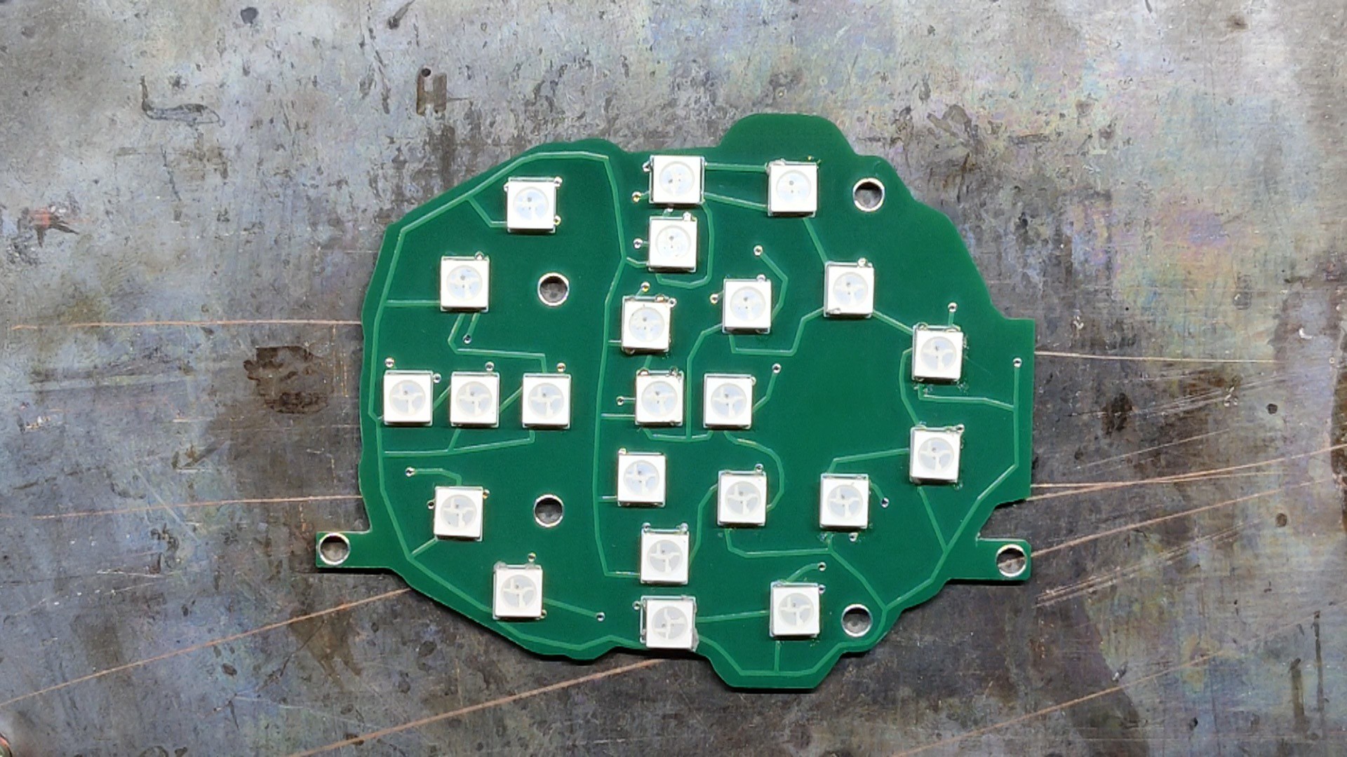
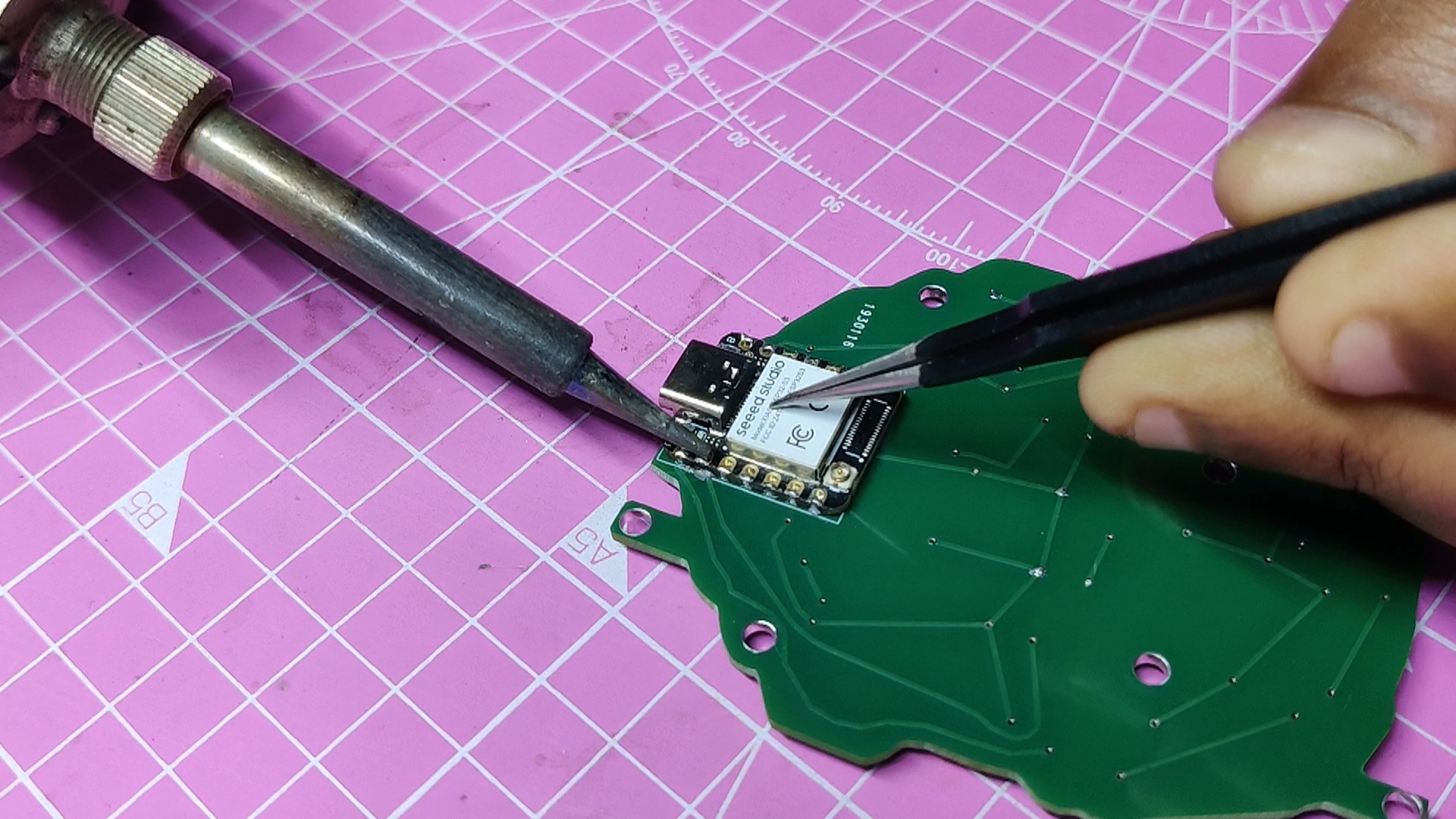
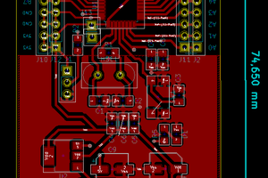
For the second PCB, or bottom board, we first prepare a schematic consisting of 24 WS2812B LEDs connected together with the XIAO ESP32S4 DEV Board.
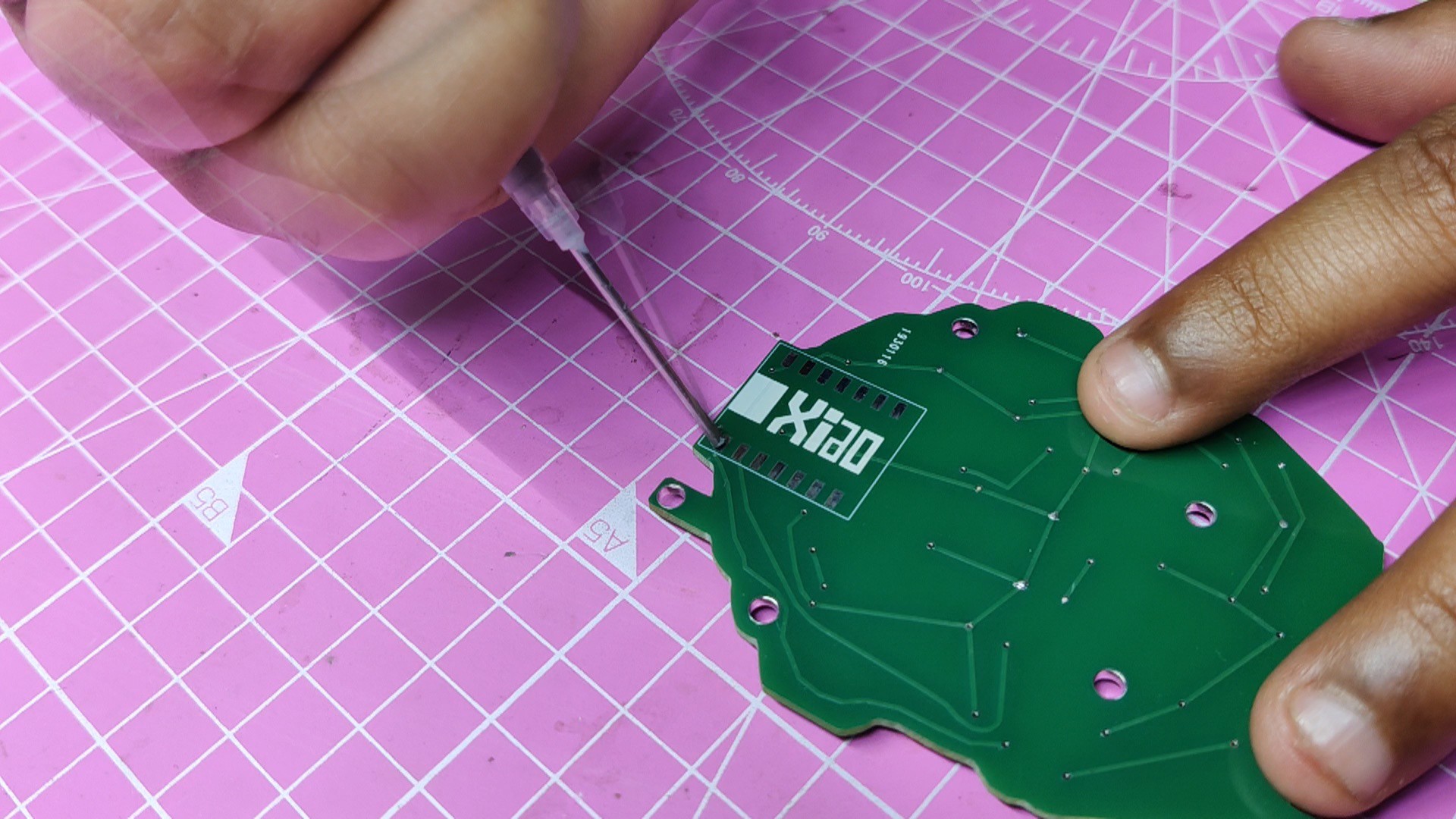
We then positioned the RGB LEDs on the second board's top face, and XIAO is positioned on the bottom face.
Seeed Studio Fusion Service
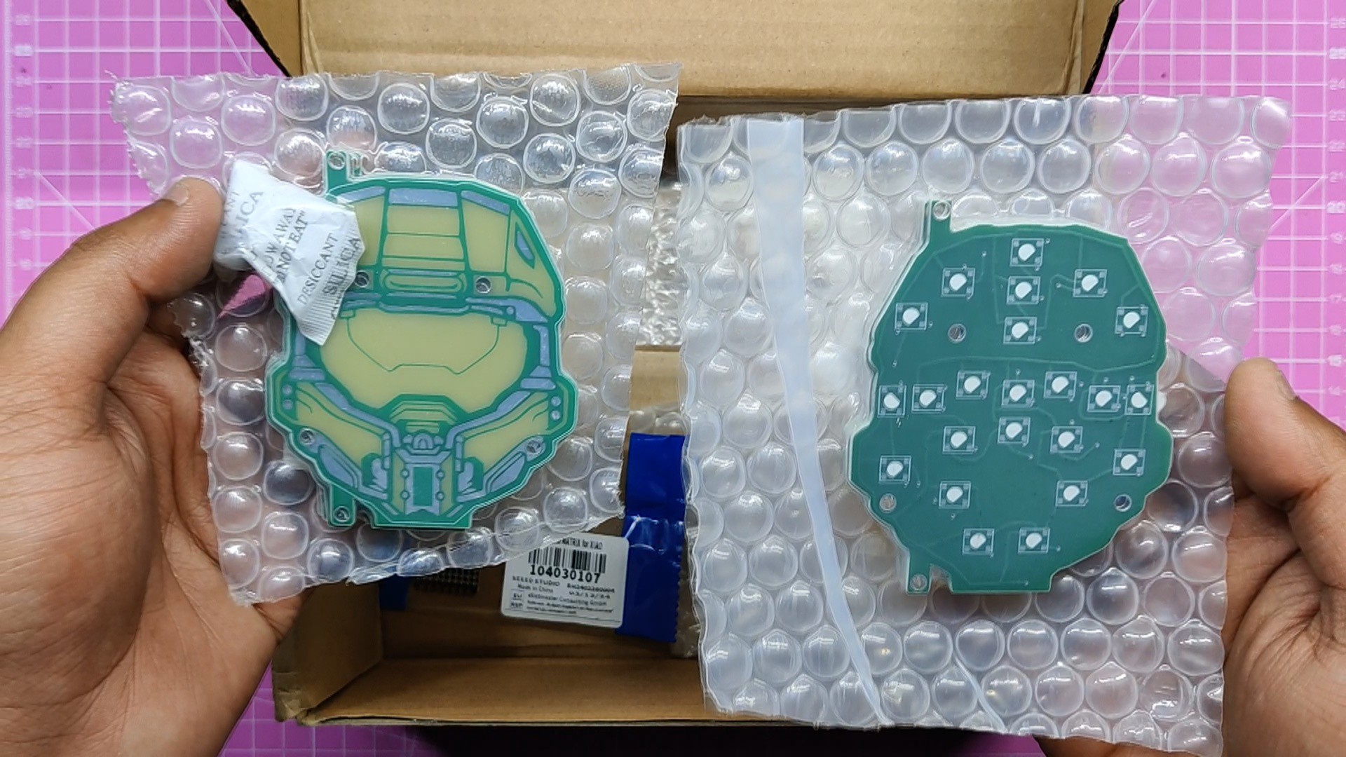
After finalizing both PCBs, we exported their gerber data and sent them to Seeed Studio Fusion for samples.
Two orders were placed, one for the front board and one for the back board; both orders were placed in a green soldermask and white silkscreen.
PCBs were received in a week, and their quality was super good considering the rate, which was also pretty low.
Seeed Fusion PCB Service offers one-stop prototyping for PCB manufacture and PCB assembly, and as a result, they produce superior-quality PCBs and fast turnkey PCBAs within 7 working days.
Seeed Studio Fusion PCB Assembly Service takes care of the entire fabrication process, from Seeed Studio Fusion Agile manufacturing and hardware customization to parts sourcing, assembly, and testing services, so you can be sure that they are getting a quality product.
After gauging market interest and verifying a working prototype, Seeed Propagate Service can help you bring the product to market with professional guidance and a strong network of connections.
 Koen van Vliet
 PCB designer
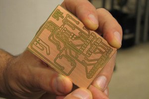
 Adem-ADATEPE