 Patrick Van Oosterwijck
I checked the solar charging capability with a 18 V nominal panel. The MPP voltage for this panel is 15-16 V, so I added a 4.7 kΩ resistor to the MPP pads, which sets the MPP voltage to 14.6 V and put it outside.
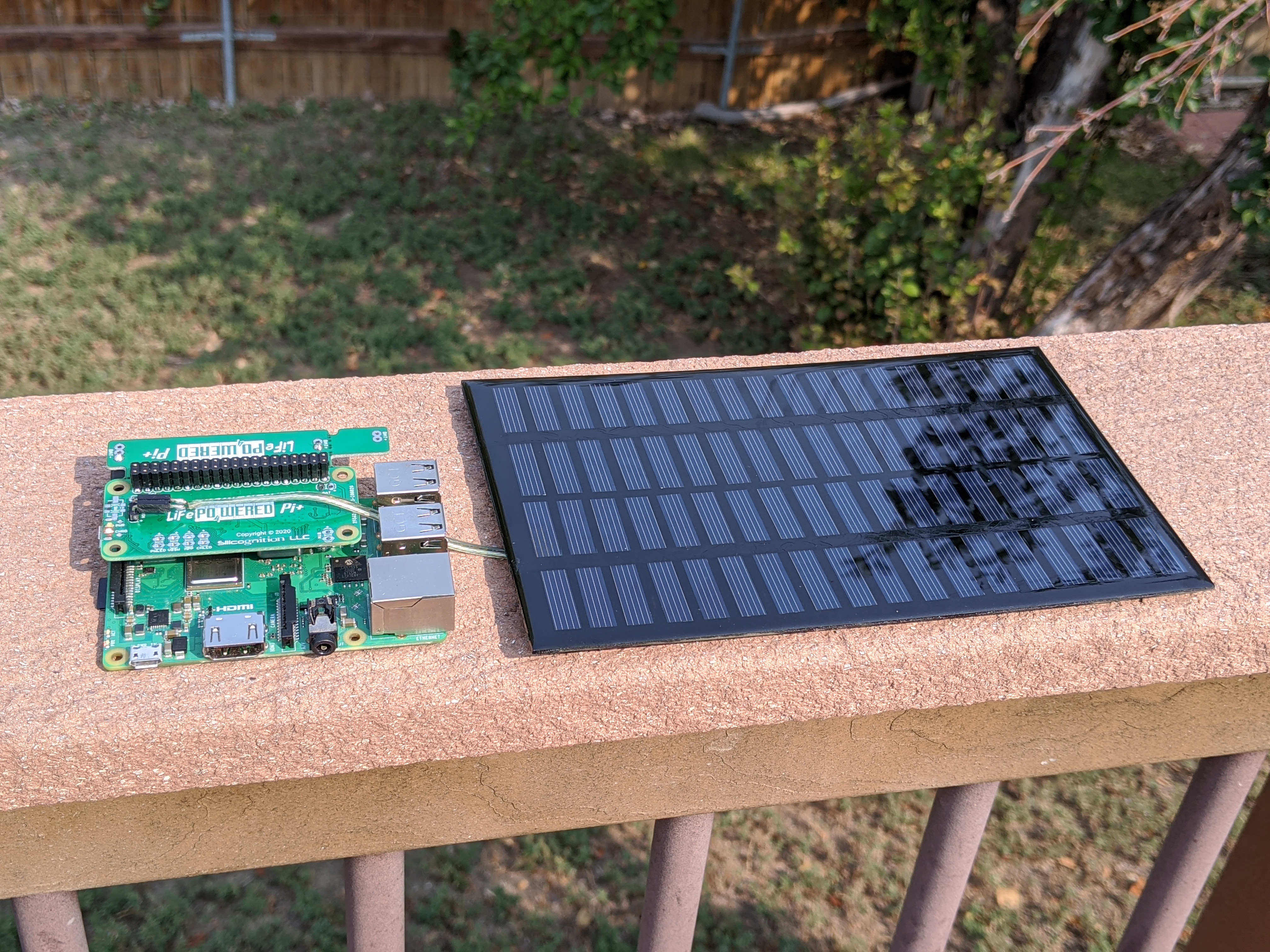
I measured that the solar voltage was being regulated to 14.7 V, close enough considering part tolerances. Note that the panel in the picture was for testing only, this panel is too small to keep a Pi running. It kept the charge up jut barely with a Model B+ in direct sunlight, a Pi 3B+ was too much. For practical use, you need a bigger panel, or use a lower power Model A+ or Pi Zero.
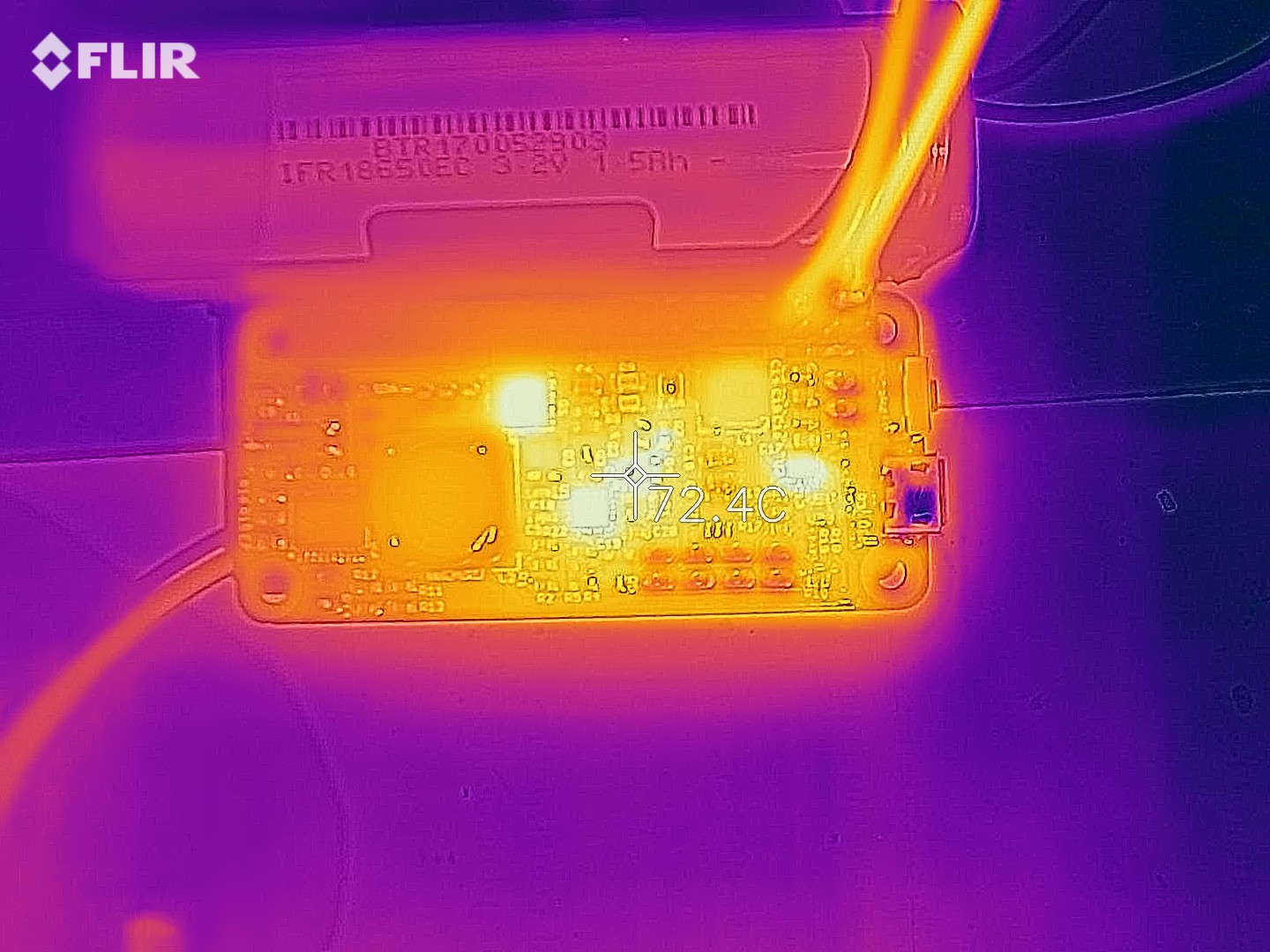
Next up, I tested heat generation under high load with high input voltage. I applied 20 V on the input with 2 A load using my electronic load:
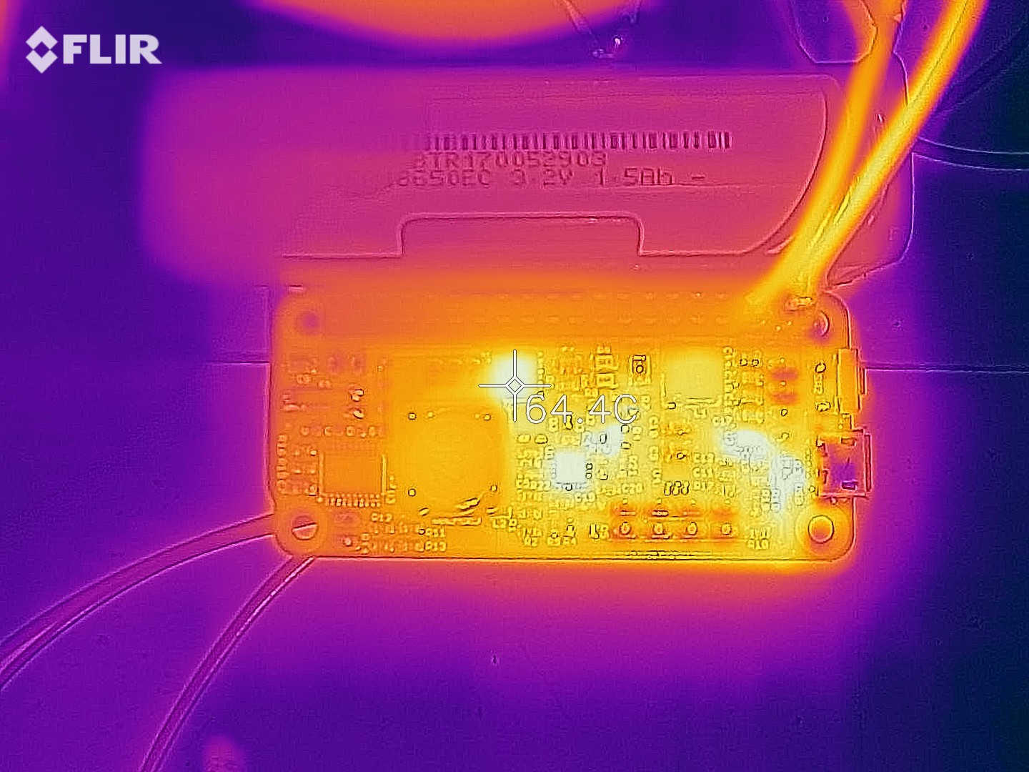
The switching transistor, which was a hot spot in the old asynchronous design with high input voltage, is running at 64 °C, which is just fine. Other hot spots are the charging chip (not entirely expected), the pass transistor and boost converter (expected), and... what's that hot spot near the USB connector? Oh, the charge LED current limiting resistor.
How much is that thing dissipating? A quick calculation shows at 20 V input, this resistor dissipates about 0.36 W. Oops, it's a 0.1 W resistor! :) Gotta do something about that. The 19 mA or so flowing through the LED may also be part of the reason the charge chip is getting hot, but most likely it's due to the built-in linear regulator that needs to drop 15 V at 20 V input.
I changed the LED current limiting resistor from 1 kΩ to 4.7 kΩ, which should keep the current low and the dissipation in check at 20 V input. On the other hand, at 5 V the current may become so low (less than 1 mA) that the LED is very dim. Let's check that:
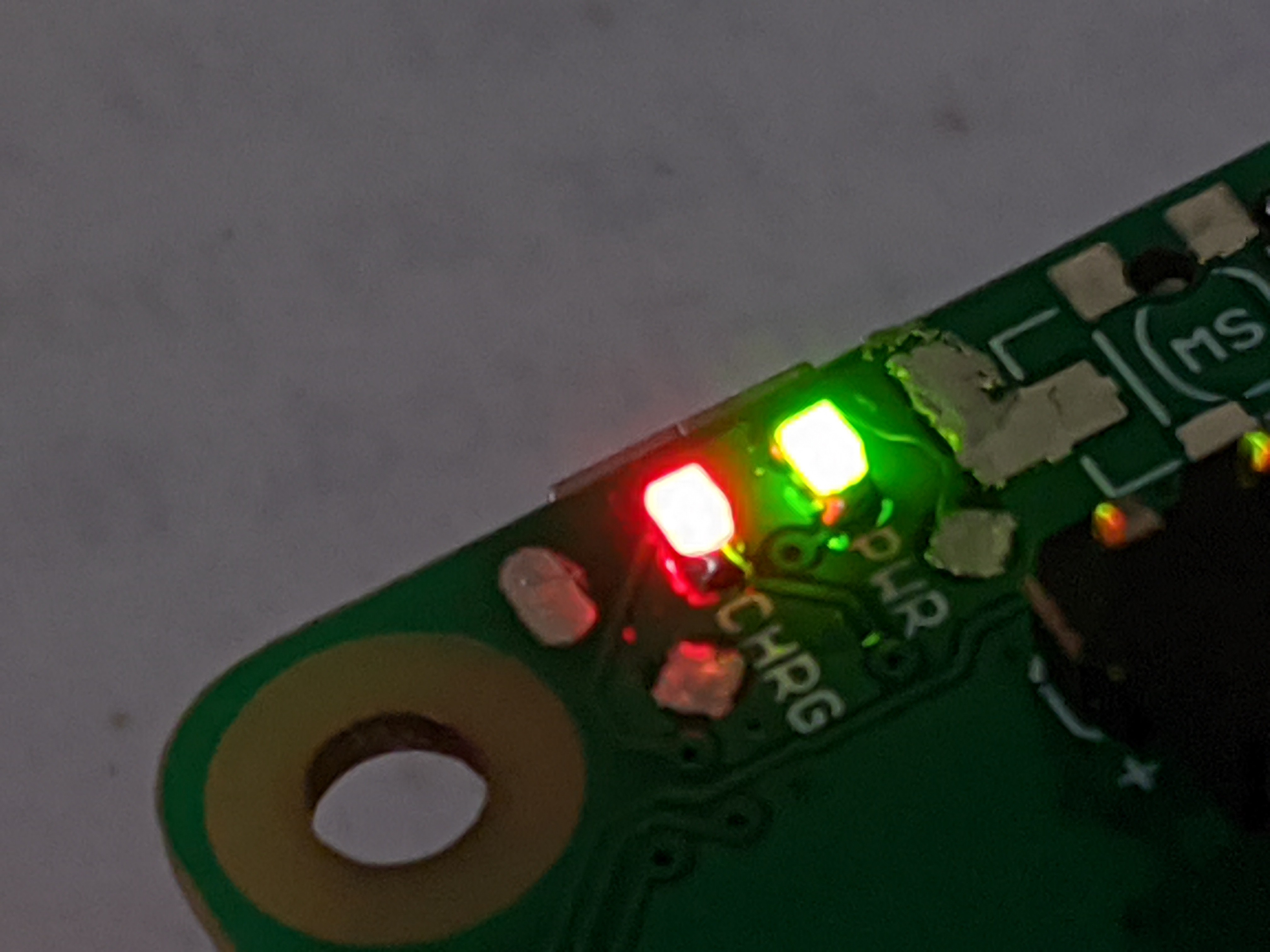
Looks alright to me, the red CHRG and green PWR LEDs seem to be about the same brightness.
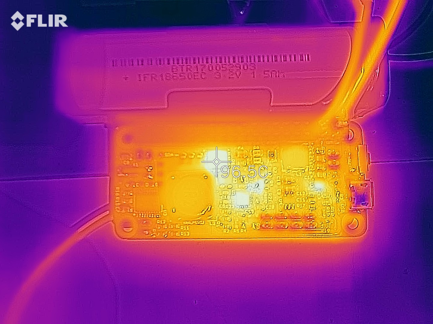
Time to redo the high voltage input load test. This time though, I also discharged the battery all the way, so the system has both charging to do and the load to supply. Not sure if it made much difference, but hey, let's try to do it right:
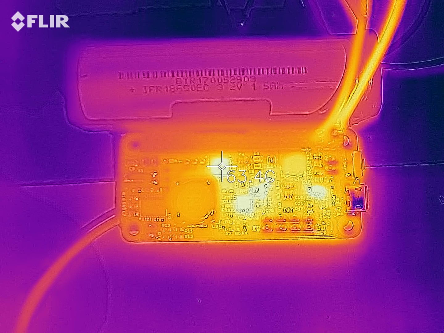
First thing of note is that the hot spot near the LED current limiting resistor is gone. Good. The switching MOSFET's temperature is about the same as before. The hottest spot is actually pass resistor Q4:
Maybe I should investigate if there's a part with lower RdsON than the SSM3J338R,LF I'm currently using? On the other hand, the temperature it's at isn't really much to worry about.
Let's see what happens if we bump the input voltage up to 24 V. In the previous asynchronous design, things would get hot enough I feared for thermal runaway.
As expected, the switching transistor is the hottest spot now. Too toasty for comfort, but it seems stable.
Let's be really mean and also bump our load current to 2.5 A at the same time!
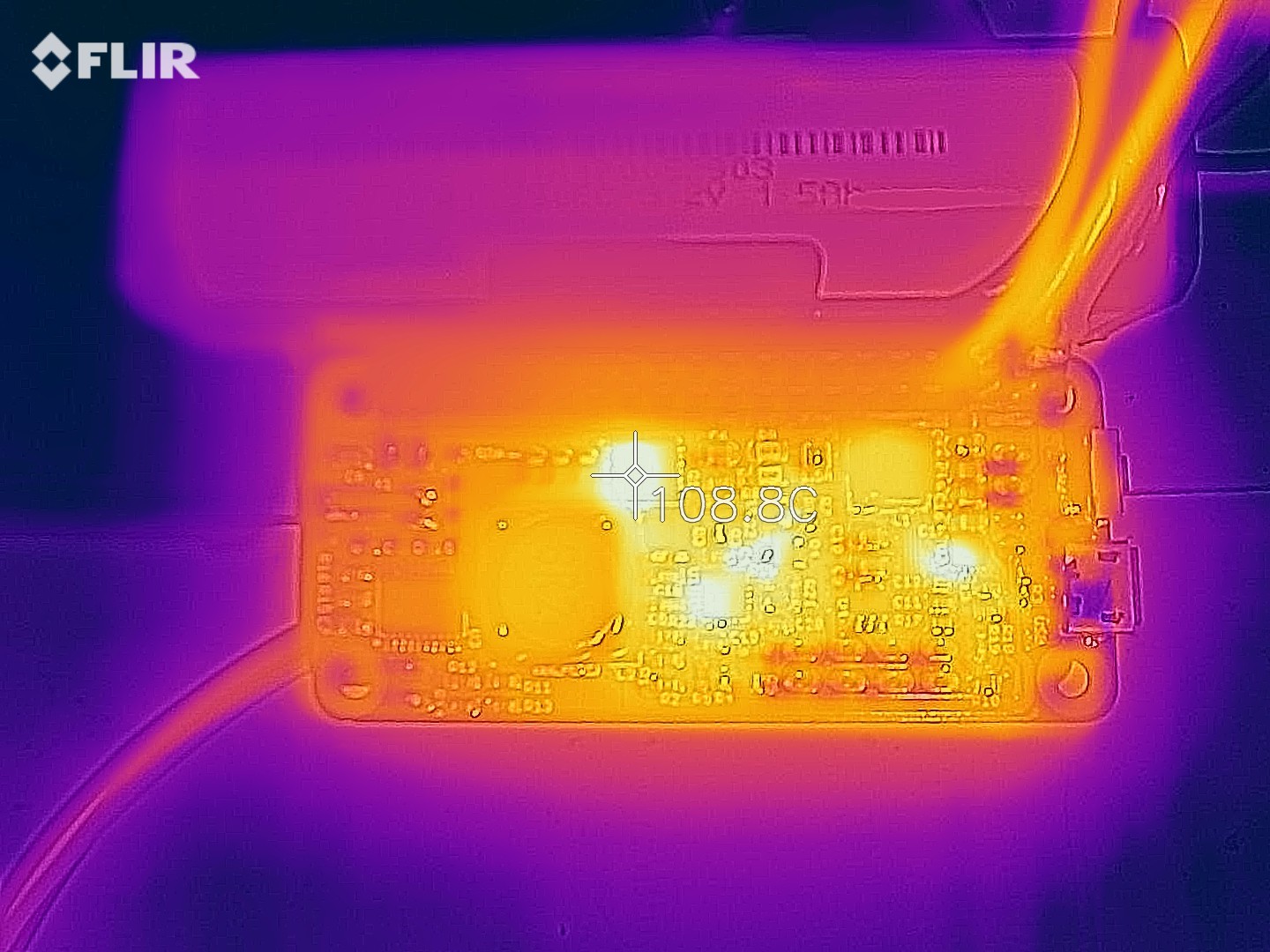
Ouch, hot! Seemed stable though. But don't do this, that's just mean. I just do it to prove the design has plenty of headroom.
One important thing to note in all these tests is that the prototype boards I ordered are standard boards with 1 oz copper, while production LiFePO4wered/Pi+ boards have always used 2 oz copper for improved thermal performance. So I consider what I'm seeing here quite good, and it will only become better on a production board with 2 oz copper, lower conduction losses and better thermal conductivity.
Discussions
Become a Hackaday.io Member
Create an account to leave a comment. Already have an account? Log In.
Hey @Patrick Van Oosterwijck ,
already sent you an email, but maybe it's better to have those informations publicly as I digged through all informations I could find in advance too :)
We want to add a solar panel with 12V System Voltage (e.g. https://www.offgridtec.com/en/offgridtecr-olp-10w-solarpanel-12v-schindeltechnologie-perc.html) and these specs:
Power (Pmax): 10wp
Voltage (Vmp): 18.7V
max. current (Imp): 0.53A
Open circuit voltage (Voc): 22.44V
Short-circuit current (Isc): 0.58A
max. system voltage: 600V
Which voltage value should we consider for calculating the needed capacitor?
Is it 12V for this case, or 18.7V to use in the provided formula: RMPP = 51815 / (VMPP – 4.66)
Thanks for your help!
Are you sure? yes | no
Hi Moritz, sorry for the slow response. You would use the Vmp value of 18.7V.
With that value the formula gives you 3690 ohm. Closest standard value is 3.9K, which if you reverse the formula gives an MPP voltage of 17.95V. Close enough, and on the right side of "off" since the power drop off power on the lower voltage side is more gradual than on the higher voltage side, and at less ideal lighting conditions the MPP voltage also tends to be lower.
Are you sure? yes | no
Thank you so much!
So for a solarpanel with Working voltage (Vmp) of 20V the same resistor should be fine too? Or should we go for a 3.3K ?
Are you sure? yes | no
For 20V, something in between would likely be best. Like I said, I don't like going over the listed MPP voltage for a panel since the power drop-off is very quick. If you can go with E24 resistor values, 3.6K would be good, 3.48K from the E48 series would be better. If you really need to stick to E12 values, probably 3.9K is best, but consider using resistors in series or parallel to get closer.
Are you sure? yes | no
Awesome this works quite well so far :) Altough we should think about some cooling. Any recommendations what to use for cooling, together with a RPi 3A+ & another board on top?
Are you sure? yes | no
No particular cooling product recommendation. In general, for a RPi 3A+ a small heat sink on the processor and a fan providing airflow over the complete system (flowing between the stacked boards) is a good idea. The particulars are often dictated more by the case than anything else in outdoor applications.
Are you sure? yes | no
Hi Patrick, thumbs up for that beautiful work. Just well received my first LiFePO4wered/Pi+ Board last week, bought on tindie. Now I saw you're already working on a next Revision. How are Tests going so far? Any idea when this will be launched?
Are you sure? yes | no