
 Rue Mohr
-
The 7 segment decoder, done wrong.
11/01/2023 at 19:56 • 16 commentsHi,
I'm Rue Mohr, you might know me from such places as the internet, the information superhighway, or the world wide web.
Today I'd like to tell you about an adventure in optimization of a 7 segment decoder.
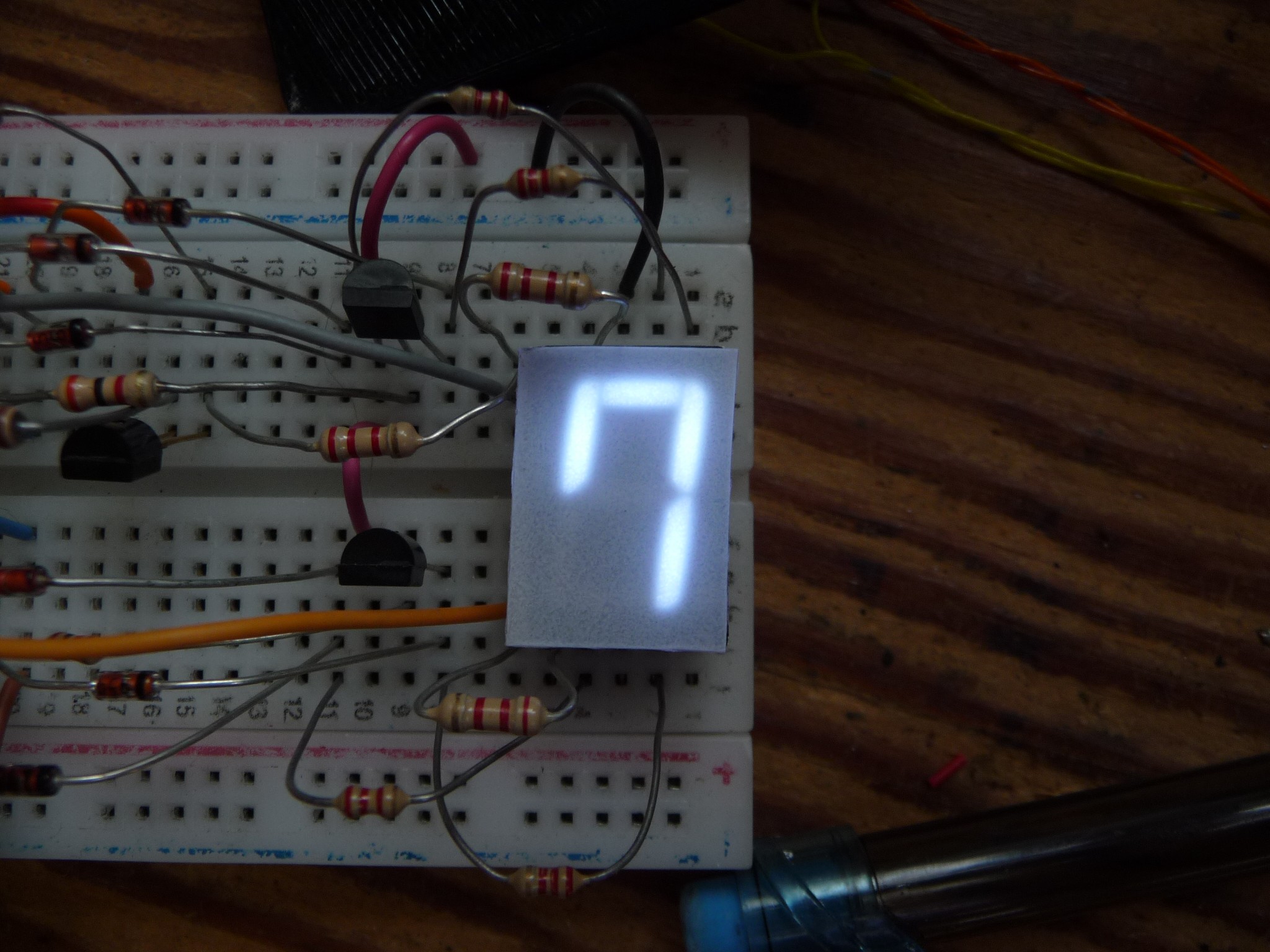
![]()
(7 segment display with the highly debated hook applied to the digit "7", OOOoooo)
For <lots of> decades people have fought with designing display decoders to take 4 bit BCD and generate 7 segment digits with it. Its not easy, there is a lot of decoding and re-coding involved.
![]()
(solution by the worlds greatest logic engineers, immortalized in the 7447 logic chip)
Granted, today we can just use an FPGA, CPLD, PAL, or 48MHz RISCV to perform this 4 bit to 7 segment decoding for us, but, is there a cheaper way?
![]()
(Could a way be found to take a few diodes and transistors and produce the coveted 7 segment patterns?)
My proposal was to ditch the BCD input. The particular application I have targeted for this (ok, yes, its a CLOCK...) does not NEED to be sending BCD to the displays. I do want the codes to be 4 bit to reduce wire count (otherwise, just sending the 7 segment patterns directly to the displays is easy enough)
![]()
(Super evil BCD bad boooooo, Hissss...)
Is there a 4 bit pattern that could more easily be converted to a 7 segment font than BCD? I decided to put a bounty* on the solution....
Now this puzzle has a few dimensions, there are 2 ways to make a 1, 6, 7, and 9 on a 7 segment display, that means there are 16 different 'fonts' that can be used. Also the choice of which 10 of the 16 4 bit codes to use is completely open.
(* the bounty was nothing, so there wasn't an overwhelming set of answers)
![]()
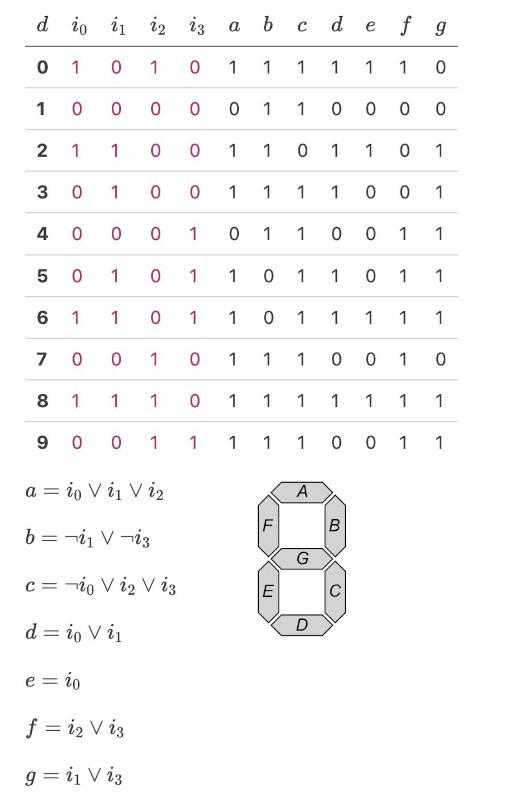
There were a number of answer that came back, one of them seemed unbelievably simple. (Don't get me wrong, I'd been working on a solution myself, but I'm REALLY BAD at this type of puzzle)
![]()
The above equations resolve into only a little bit of circuitry. That became even less when @minusYCore pointed out an optimization I'd missed on the G segment.
Now, I can't prove this is the simplest decoder that can be made for 4 bit to 7 segment, but Its in the right order of magnitude. Part of what makes this tiny is the direct bit-to-segment relation of e and f.
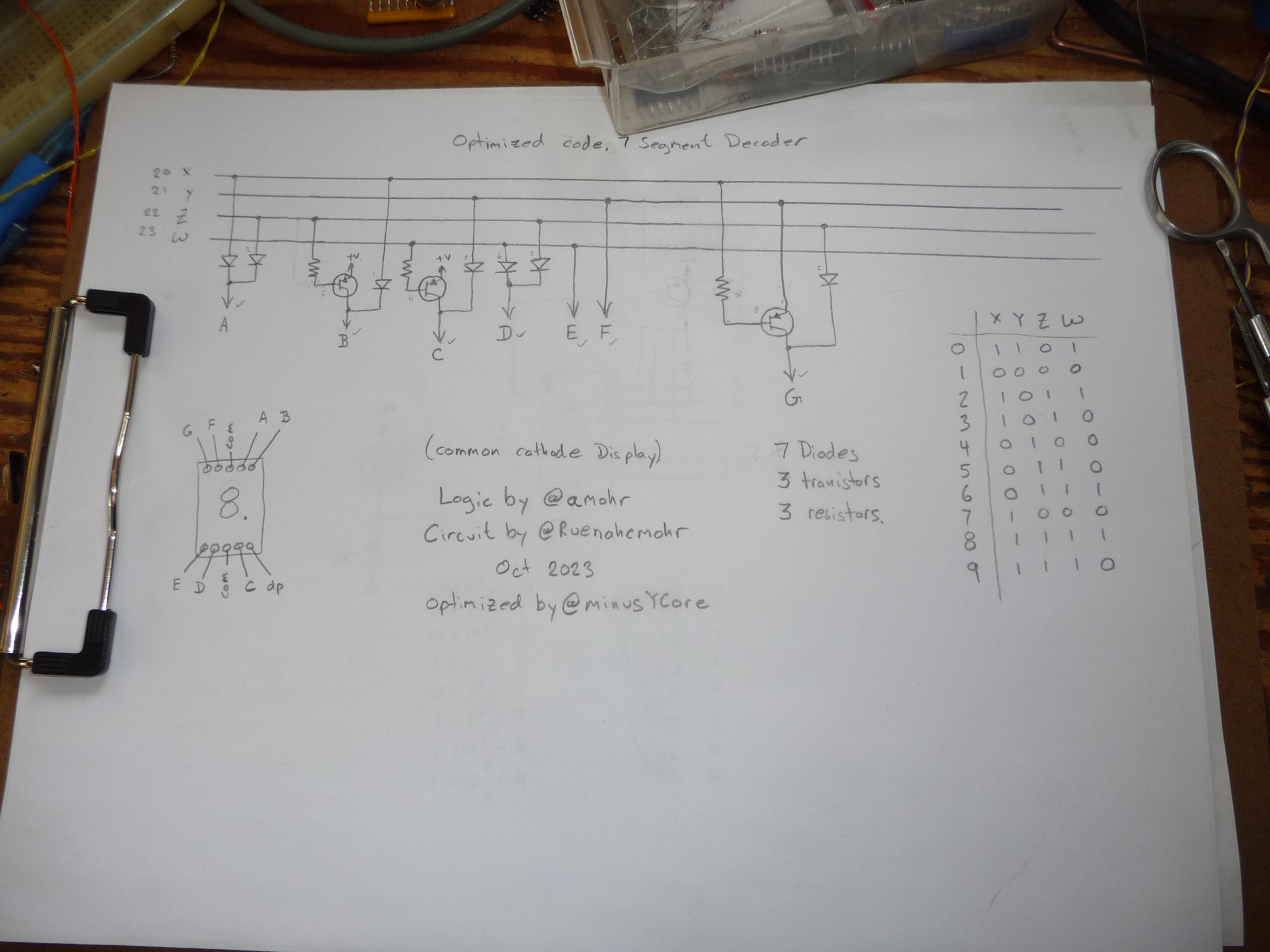
![]()
(Only a few components to implement the logic worked out by @amohr)
At this point, the circuit had already been simulated by a few people, and, with quirks, confirmed to kinda work.
But I build them anyhow :]
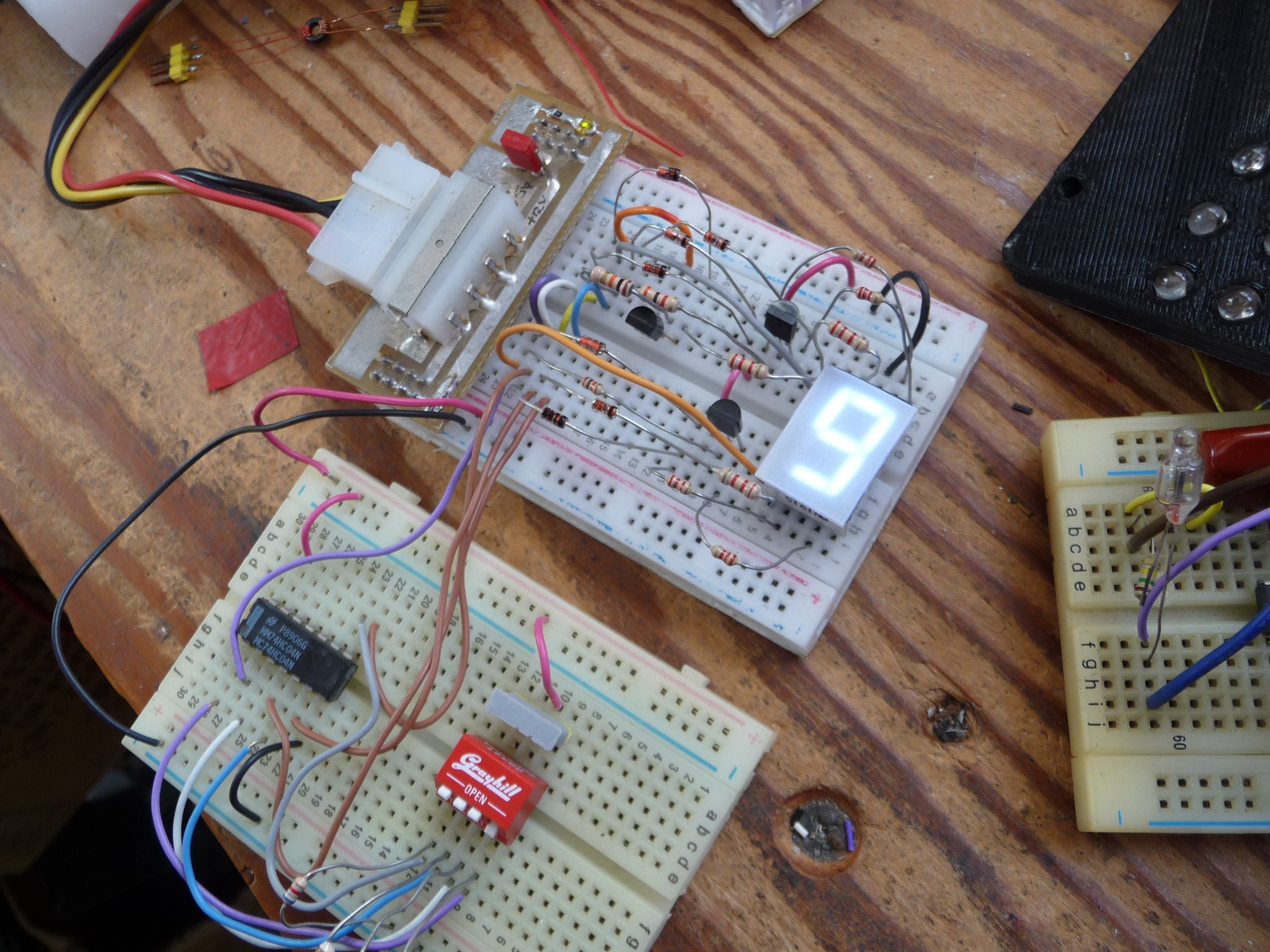
![]()
(The decoder circuit is the top board)
Two small breadboards, the top one for the decoder, and the bottom one for the 4 bit input driver. Everything checked out. The next obvious step is to make a PCB that fits on the back of a 7 segment display, which, seems plausible...
![]()
(The "Train wreck" stage of designing a PCB)
Hours of kicad later.. (you don't really notice if go by) a PCB emerged.
![]()
![]()
So, the PCB has been ordered, the results will come later. In the meantime its been a great adventure. It even has hack codes (the 6 unused codes cause the logic to do 'other' segment patterns)
![]()
I would also like to give mention to work done by (twitter) @poulsfriend, @oric_iss, @likimmo.
This was another answer, it does resolve down to a bit more circuitry. (but its really close)
![]()
![]()
But... Why not use a Greenpack? CPLD? FPGA? or RISCV microcontroller?
THIS circuit, is cheaper, its 8 resistors (which you need anyway) and a total of less than 20c in discrete components. (at shipped, hobby volume prices)
It has not been proven to me yet, that you can actually GET (with shipping) a 10c microcontroller FOR 10c. (yes, I know there have been a lot of articles written about this) You tell me the source, and I'll tell you the price they give me (yes, unit price with shipping included)
Rue M.
-
The LM555, done wrong.
03/22/2023 at 04:39 • 0 commentsPages? lets try this...
Hi I'm Rue, you may know me from such places as the internet, the information superhighway, and the world wide web.
You may be familiar with the practice of 'circuit bending' often used by hardware hackers to create musical instruments that in turn are used to create compositions questionably referred to as music. ( ;] )
I am indeed a type of minimalist, as such I prefer not to bend circuits, but to bend chips.
I have come to you today to talk about bending the LM555 chip. I know you know this chip, everyone knows this chip, its more famous (slightly) than the 6502, its less powerful than the Z80, and it has more gates than a PN2222. This set of bending will be done within the constraints of using the 555 as an RC oscillator, I wont get into using it as a digitally annunciating/resetable window comparitor that drives a relay, or a crystal oscillator, or a logic gate, or a monostable or its uses for vogon face detection, just an oscillator.
![]()
(Now I just dive in)
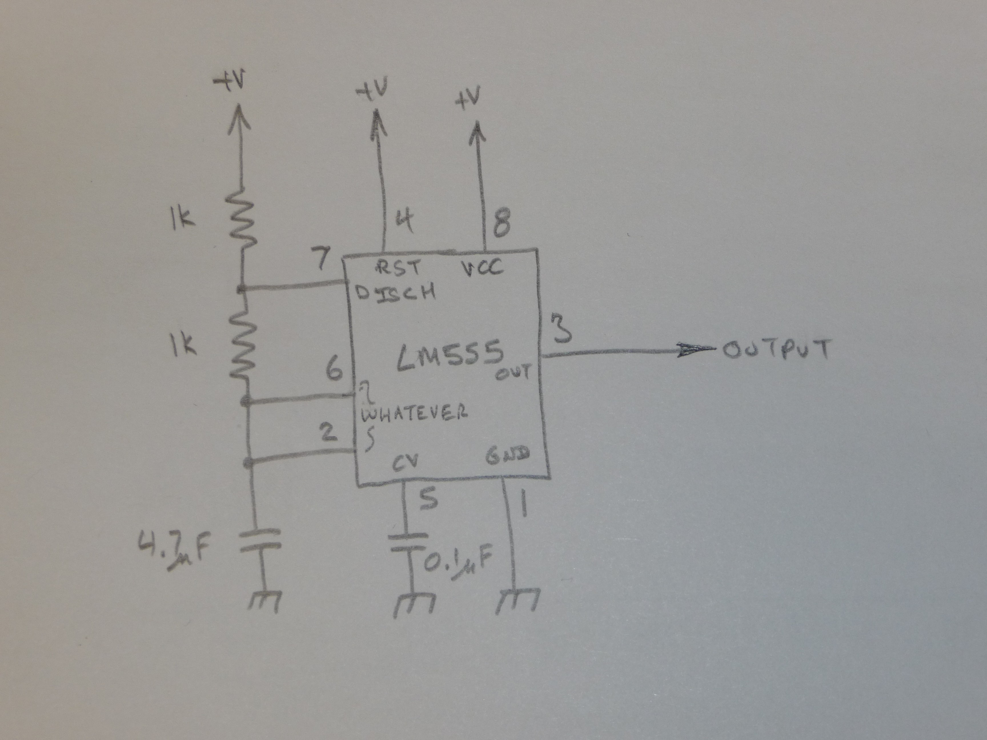
So, here is the standard 555 circuit you might be familiar with, its... the ( quite boring ) standard circuit...
![]()
So, there are a lot of parts here we don't need.
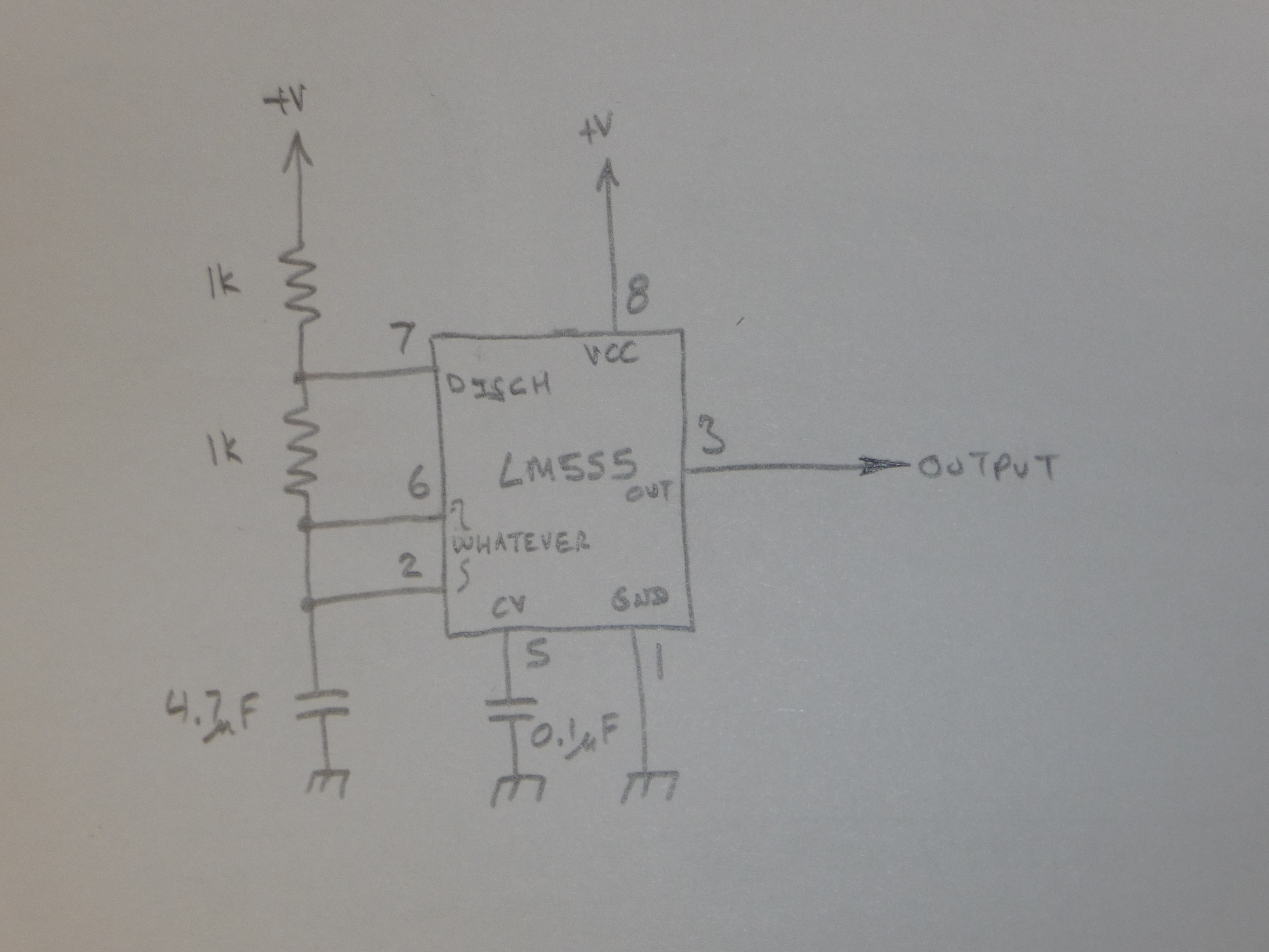
Lets start with that wire to pin 4. If your using a 555 that is NOT CMOS, it will pull up pin 4 past the reset voltage just fine on its own. so, you don't need that.
And we have almost the same circuit.
![]()
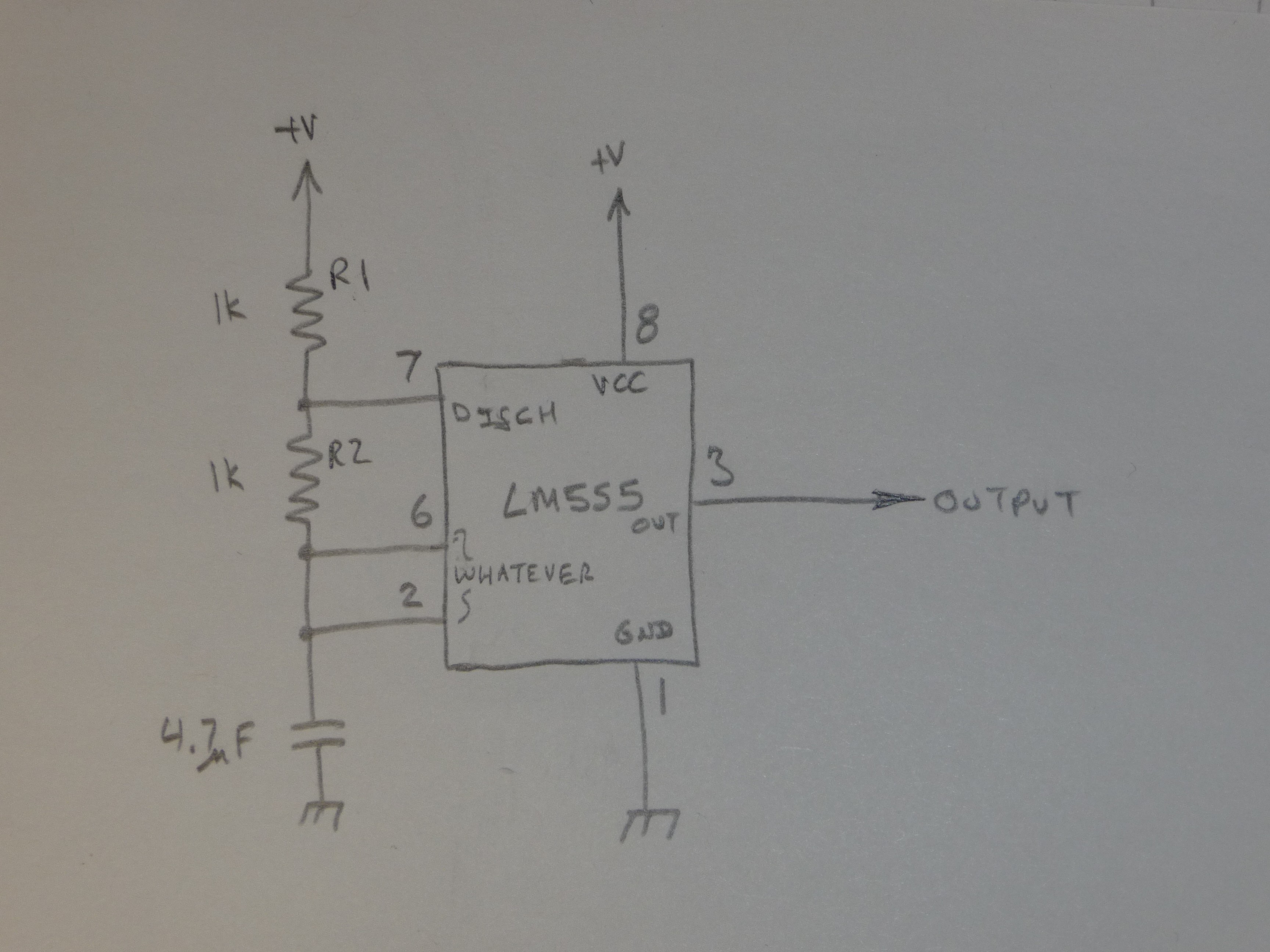
Now, if your using a clean power supply (of course you are) you don't need the capacitor on pin 5.
Nice, we removed a real component. 🎉
![]()
This circuit works by a sort of funny its-not-a-voltage-divider. The capacitor is charged thru the two resistors, and when the chip goes into discharge mode, it switches pin 7 to ground, and discharges the cap thru R2. (whilst grounding out VCC thru R1 )
But... we don't need to do that.... Pin 3 goes to ground at the same time pin 7 does, but pin 3 goes to positive power the rest of the time. This can be used to charge AND discharge the capacitor.
So we can ditch a resistor and put the other one between the 2,6 node and 3
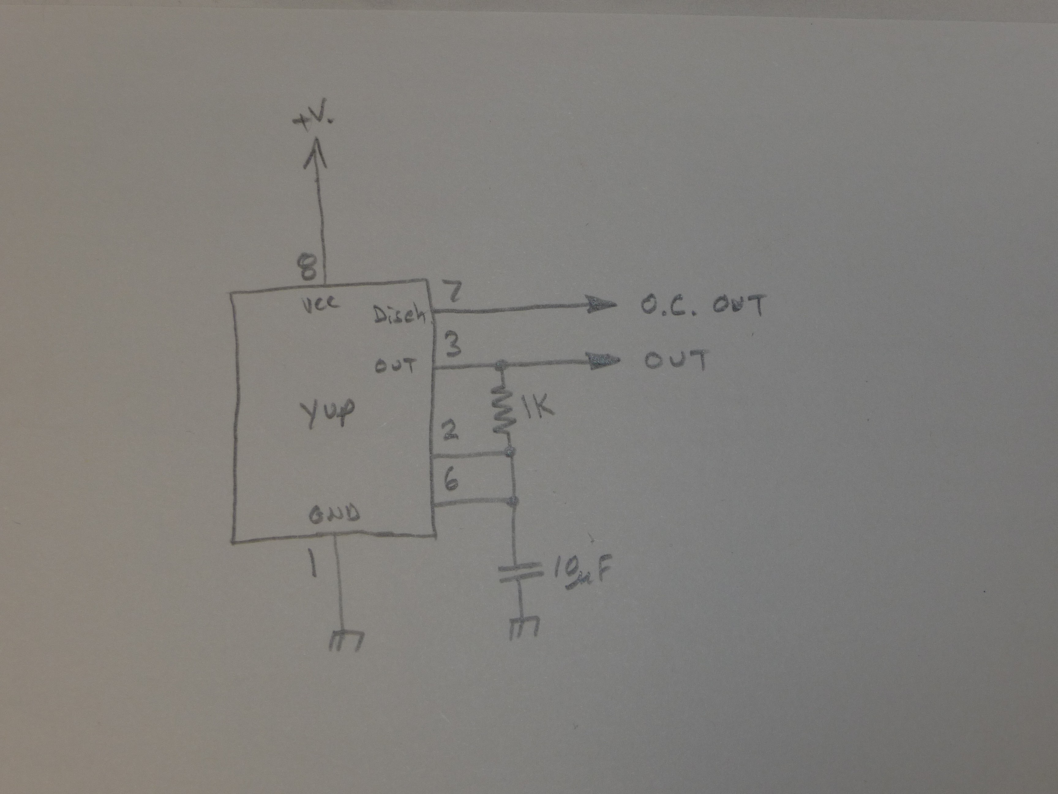
so we end up with this..
![]()
If you only want an output that is open collector (drive a relay, or LED!) , pin 7 is your friend! Pin 3 can still be used as a digital output.
That circuit is the one I almost always use for a 555. its duty is <close to> 50% and, including the 555, its only 3 parts.
shame I'm still stuck with that pin 2,6 thing :/
Mohr wrong
Did you know a capacitor blocks DC offsets? so what? right? Well, your timing capacitor does not have to go to ground, it can go to ANY stable dc voltage. And in this circuit, we have 2 of those.
Just to be more wrong, lets move the timing capacitor to Vcc instead of ground.
![]()
There is another thing we can do, we can turn the circuit into a 2 wire flasher (kinda)
How? WELL, The CMOS version of the 555 (yea, add that wire back to pin 4) consumes only TINY amounts of operation current. unlike the current needed to charge that big timing capacitor (use a big one!) So, using that we can make an oscillator that draws pulses of current.
![]()
[abrupt end of article, but actually, in fact, the end. Have a nice day, BYE!]
My Projects
My Pages


Things I've Built
Raccoon detector
Simple device to detect if raccoons have been present. If they have the detector medium is modified. May need some refinement, generally works.
Shop mascott
Shouldn't we all have one? Knee caps, hehehe
Local datasheet search engine
pdf search engine for my local fileserver. I like to keep local copies and often have fun finding them.
BF interpreter on avr
The BF code is stored in the avrs eeprom memory, which can be flashed seperatly from the firmware that executes it. Fun project, pointless.
DIY solder pot.
oh I'm sure its too dangerous for you tho :) This thing has gone thru about 7 thermal cycles and the bulb is still ok.
current sensor shunt from pcb
current sensor shunt from pcb build log: http://ruemohr.org/~ircjunk/tutorials/elex/cursense/main.html
nifty shaft connector
this comes in really handy, easy to do. borderline as a 'project'!? cmon....
propellor for derigidagble... blimp
how to make a nice simple prop. I used the mascott in the build log. http://ruemohr.org/~ircjunk/tutorials/mech/prop/prop.html
Gearbox
If you build a lot of robots using scrounged parts, it helps to know how to make geraboxes. build log: http://ruemohr.org/~ircjunk/tutorials/mech/gearbox/gearbox.html
linear actuator made of hardware store stuff
copper pipe and fittings.
3 servo hexapod
so not the way to doa hexapod, but it was fun
clumbsy roaming robot
Always getting itself into trouble. This is a drive/steer type robot. it uses an onboard pc with dos and qbasic software.
wheeled platform for robotics
This little piggy went to ebay. I hope whoever has/had it had lots of fun!
serial controlled robot for tele-operation
ROV than isn't it? This WAS controllable over IRC. I couldn't get anyone to do anything usefull with it while it was online and a chap by the name of pepsi kept using exploits to wind up the control cable.
tracked development robot
This little robot was designed for testing out navigation and software ideas in general.
Lawn recovery robot
when you need more than to just maintain, when you need a bull headed robot to recover your yard. Yea, its sideways, what of it?
Lawn mowing robot
100% autonomous lawn mowing robot. Runs a motherbaord with dos + basic it still works, its about 12 years old now (lots of upgrades)
generic robot platform
I wanted to solve the worlds robot platform challanges, oh well.
coffee bot
robot designed for delivering coffee to the programmers in the office. didn't get finished :(
18 axis wireless rov hexapod
doing its dead bug impression. Currently has power distribution problems, really built as a software test platform photo blog: http://ruemohr.org/~ircjunk/robots/buddy_III/
Wireless computerized rov
3 seconds latency on the video feed, wifi sucks
Teathered ROV
Look ma! no latency! Teathered ROV
Cardboard gimbal
Enjoy the build log: http://ruemohr.org/~ircjunk/robots/ballbot/
robot arm
'arm 4' a stepper based robot shaped after the ABB irb 1400 love that irb 1400...
absolute positioning system
ok, not finished, but another fine build. log: http://ruemohr.org/~ircjunk/robots/abspos/position_scanner.html
crystal tester
Did you know clock crystals can die? I use a lot of scrounged parts, this is a lieel circuit for testing if a crystal is ok
Audio selector switch
I wanted electronic source selection. http://ruemohr.org/~ircjunk/projects/audioswitch/main.html
odanamanater
Measures wind speed! never got readings from this, but it was a nice build.
Trike
Every time I ride my bike somewhere I remember why I wanted to build a trike. Have you ever tried to build an ackerman steering rig?? ITS EVIL! EVIL!!!!!
Smelter
ALUMINUM CASTING! Could be handy for building a 12' mecca! This thing is made of an old furnace burner and runs on diesel. melts about 6L of aluminum from about $3 in diesel, not too bad all in all.
Solinoid servo positioner
This was a "can I?" that worked, linear position of a digital solinoid using the encoder strip of an inkjet printer and my avr firmware*. (PD loop iirc) *any of my firmware is available free on request (sigh, its not all posted yet)
reprap
I cant be the only guy in the community without one now can I?
Motor driver
A generic motor driver for shop stock to make DC servo drives, something that can take some high current bumps and grunts. PWM/direction inputs.
DC motor
Some fun playing around with building dc motors. Good way to know if building one for converting a truck to electric is feasable or not.
heat plant
Wood burning down draft gassifying 'boiler'. to save up for building a mecca, you need to cut costs on things like heating.
hoist gantry
If you want to build big, you have to have the right tools, This is part of the tool chain for building a 12' mecca.
CNC machine
Basic cnc router.
 Sam Ettinger
 Tahmid
 Florian Wilhelm Dirnberger
 mit41301