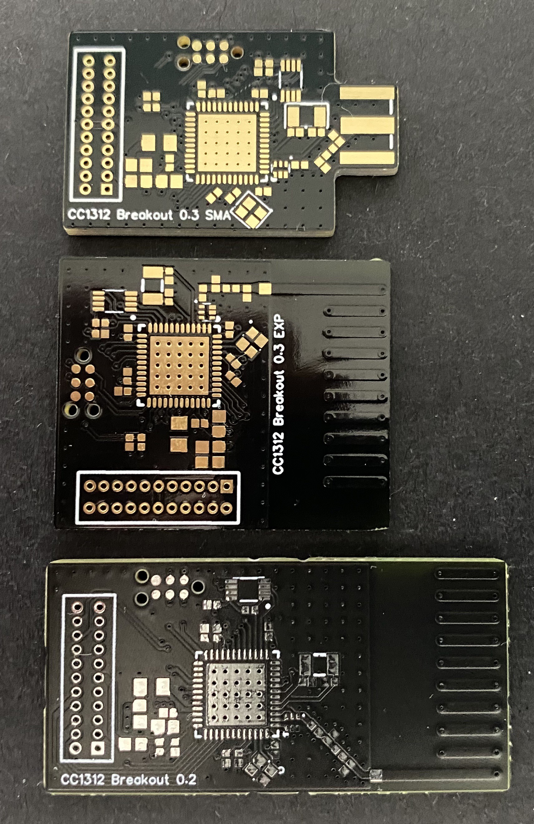
Having just received my new radio board design from PCBWay, it was time to match the antenna and test performance. Here, I will be focusing on the PCB Antenna board:
To get good radio performance, one needs to match the antenna impedance to that of the source. I use Carey Wang's excellent xavna to characterize the PCB antenna. The idea is to use a VNA to calculate what kind of filter is needed to bring the antenna's impedance (as seen from the transciever) as close to 50 Ohm as possible at the desired frequency. I leave footprints for 0402 passives to accomodate the filter, consisting of capacitor/inductor combinations.
Step 1 is to attach a semi-rigid coaxial cable to a board just before the antenna, and measure its characteristic impedance with the VNA (shown below for a 2.4 GHz/Sub-G version of the board):
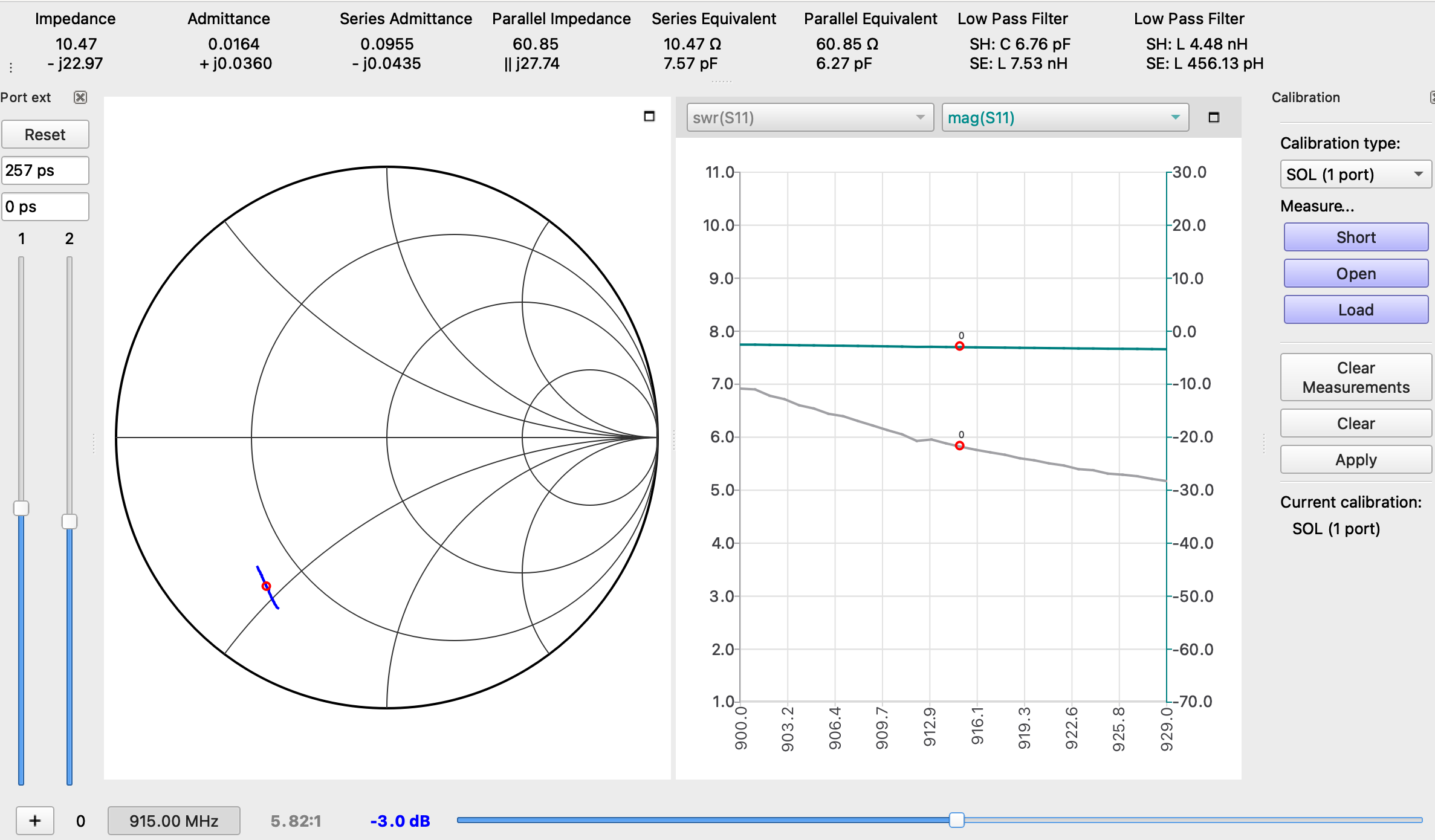
Step 2, take a measurement of the antenna without any filtering. This is the result for my new compact PCBWay board:
On the Smith Chart above, the center of the circle represents our target impedance. Here, I chose to measure the response of the antenna from 900 to 930 MHz, which is represented by the blue line. We're fairly far from our target, so definitely need to add some filtering.
I modified the software for the xavna to simplify this step: the upper right corner shows what value components to use to get a match. There are two possibilities, either a 6.76 pF shunt capacitor and 7.53 nH series inductor, or a 4.48 nH shunt inductor followed by a 456 pH series inductor.
Step 3, finding closely matching components. I use Kemet RF capacitors and Johanson RF inductors for that purpose. The theoretical values are rarely what is actually needed, and I ultimately settled on a 5 pF shunt capacitor and 10 nH series inductor, which resulted in an OK match. Another modification I made to the software is a display of "SWR" (standing wave ratio), the grey curve shown to the right of the Smith chart. This represents the amount of power reflected back from the antenna. A good match is attained when SWR is below 2:1. Here, we're getting 1.18:1 at 915 MHz, which isn't too bad.
Next, it's time to test actual radio performance! I start with TI's SmartRF Studio. First, let's see how low the noise floor is:
Around -115 dBm, not bad! This actually compares favorably to TI's LaunchPad, which is hovering around -100 dBm in the same conditions. This means we have a little more "link budget", which should result in longer range.
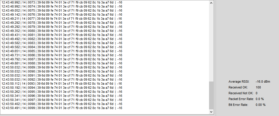
Next, let's see transmit and receive performance (using a TI launchpad at the other end). Receiving packets, both boards in the same room yields -16 dBm, that's awesome! My old design was at -19 dBm in these conditions, so that's a great improvement.
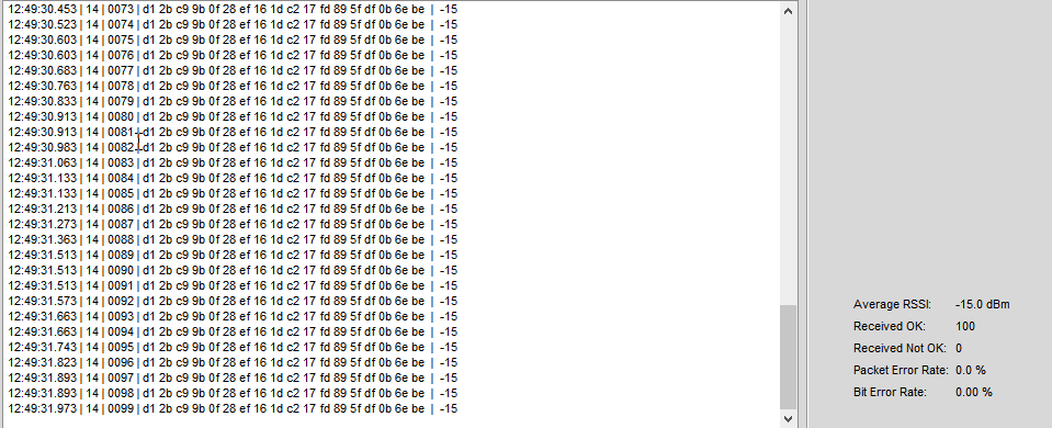
...and transmitting, -15dBm vs -16 for the old board. The PCBWay board performs better in all respects!
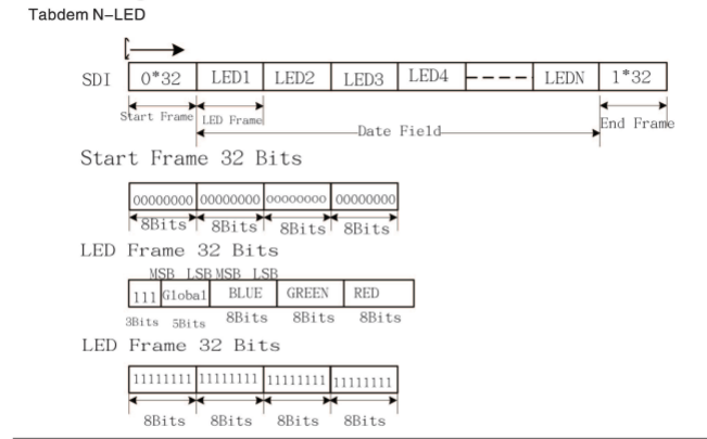
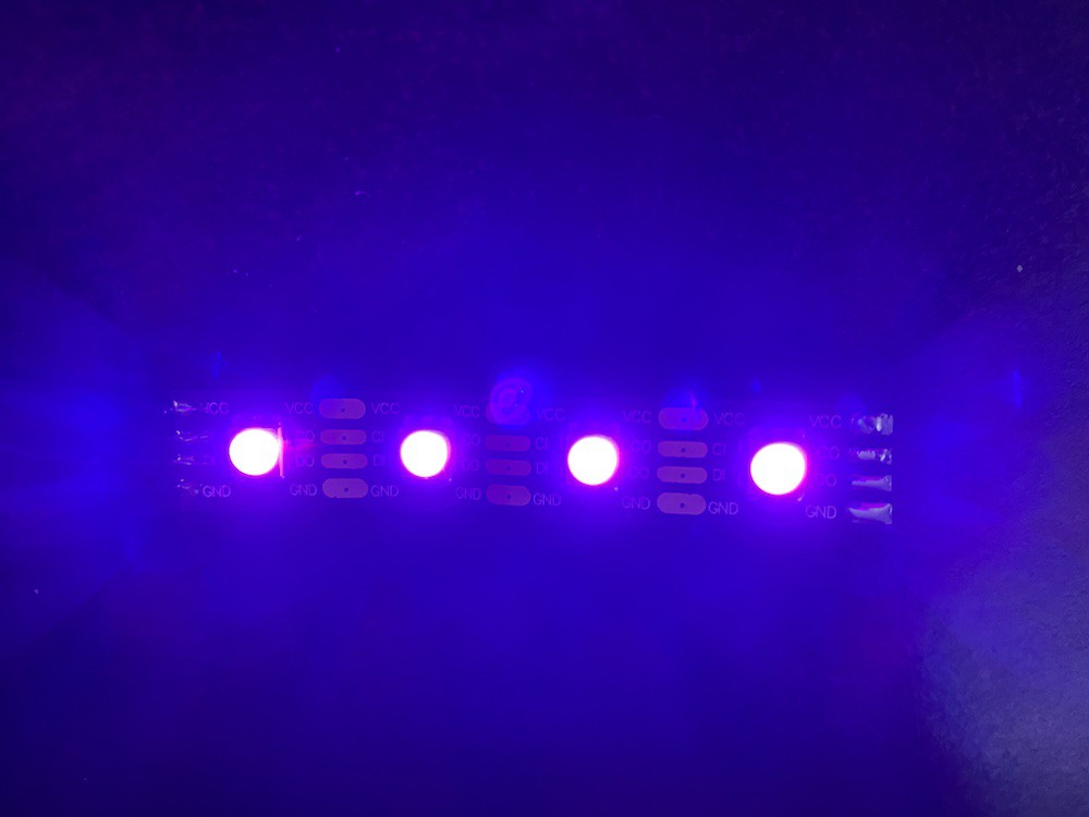
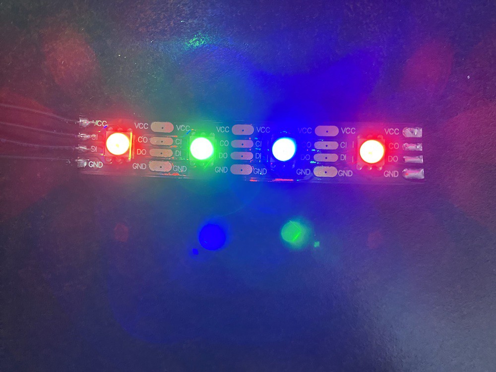
Did some tests with APA102C RGB LEDs. These theoretically work above 4.5V, but I was successful providing 3.3V for both signal and VCC, so no level shifting necessary ...at least with the batch I have! Another thing that doesn't appear to be necessary is the end frame specified in the datasheet.
If you look at the end frame, it would look like a fully lit extra LED after N LEDs. I've actually found that this is exactly what happens (eg, if you output data for 32 LEDs and add the end frame, you get a 33rd white LED, probably not what you want). I've removed the end frame from my driver, and everything else behaves as expected.
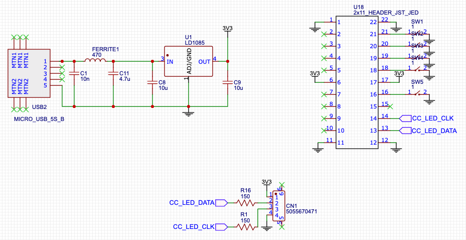
Ultra-simple circuit for use with these guys, with provisions for use without a wireless MCU with tactile switches for mode changes:
 Discreet Mayor