 Lutetium
OK, let's get started. I'm really excited to have Sam Zeloof here with us today. We've been covering Sam's homebrew ICs for a while now, and it's great to have him for a realtime chat.
Welcome, Sam! Can you maybe kick things off with a little about yourself?
 Hello everyone :-)
 We're using a laser writer for making the masks
The funny thing: The guy making the masks has also the English name Sam, but he's Chinese :D
 Sure! My name is Sam, i'm a second year student in college now and a little over 2 years ago I started acquiring and building the equipment needed to make ICs at home
 "Lanzendörfer" sounds like a very traditional Chinese surname ;-)
Last april I succeeded in making a diff amp chip, PMOS, with ~150um gate size and I've been improving things since then to now fab <5um ICs

https://hackaday.com/2017/02/25/the-fab-lab-next-door-diy-semiconductors/
The Fab Lab Next Door: DIY Semiconductors
You think you've got it going on because you can wire up some eBay modules and make some LEDs blink, or because you designed your own PCB, or maybe even because you're an RF wizard. Then you see that someone is fabricating semiconductors at home, and you realize there's always another mountain to climb.
ICYMI
I'm not Chinese, I just was looking for a job opportunity to build cool hardware ;-)
I'm originally from Switzerland
![]() Hi Sam
Hi Sam
hi adam
So how did your first year of college go?
![]() I'm not familiar with your project, but I'm guessing you are working with Si substrate. Where are you sourcing it?
I'm not familiar with your project, but I'm guessing you are working with Si substrate. Where are you sourcing it?
 hi sam, biggest question where do you get your photoresist?
Pretty well, lots of work overall but I had some great experiences and was lucky enough to start working on other stuff right away. Outside of classes, I am working in the nanofab there and have started my own lab in that department to develop new fab tools and processes. Not much info on that yet but hopefully soon I can talk more about it, make a website, etc
Yup, Si substrate. you can get small quantities on ebay or here https://www.universitywafer.com/
Sam: Our lambda is 500nm at the moment
January we'll get access to an actual fab with a lambda of 250nm!!
thethoughtemporium ! I saw one of your recent youtube vids and was going to reach out and offer you some photoresist, but couldn't find a contact button on your YT page. In the beginning I used PCB resist from Aliexpress (i think) but if you live in the US most companies will give out samples of their resists. Other than that, make friends in the industry...
The entire PDK and process flow will be published online
![]() am i able to purchase one of your homemade ic's
am i able to purchase one of your homemade ic's
![]() I'm guessing you are working with already doped wafers?
I'm guessing you are working with already doped wafers?
Yeah, at the moment 4 inch, pdoped, single side polished, prime wafers, but the process is designed
haday, yup. Commonly for NMOS circuits you start with a p-type bulk doped wafer, and the opposite is true for PMOS. For CMOS, you can start with either but commonly p doped are used, then to make P channel devices you implant a N-type well
in a way, that you just have to recalculate the dose for the nwell and pwell
Exactly, Sam!
Ya pcb resist is just about all I can find. getting su-8 or similair seems to be a monumental task which seems silly considering. Was worried the answer was gonna be "make friends in the industry". Which evidently it is.
I''l update the document in the next few days:
https://download.libresilicon.com/process/v1/process_hightech_steps.pdf
you can order small quantities of SU-8 through any school or business
Please join next Sunday, 9pm HKT on murmur.libresilicon.com our Mumble sessions!
please!
 https://hackaday.io/project/58287-bipolar-dudes will be interested :-)
![]() You mentioned you are completing your toolchain for 2 years now. How many tools were required to complete a fist prototype? Can you give us a gloss-over of the procedure?
You mentioned you are completing your toolchain for 2 years now. How many tools were required to complete a fist prototype? Can you give us a gloss-over of the procedure?
FETs are easier, in my opinion, to make. You can make them with only 1 doping step, BJT you need 2 and the base junction depth needs to be controlled very precisely
 Hey hackadoodles - new project log and video. We did an inertial test and weren't decapitated. I call that a win. https://hackaday.io/project/165038-grinder-minder/log/167085-inertial-load-testing
We've got tripple well
ah
i watched your lab tour video. quite an impressive setup. Was actually thinking of picking up a DLP projector because of your demos of using it
and SONOS flash :D
--> https://download.libresilicon.com/process/v1/process_hightech_steps.pdf
thanks, yeah DLP projects work quite nicely for maskless litho. I had great results with a newer 1080p projector and stock Hg lamp
wanna have a talk on mumble?
what's the smallest feature size you've managed with the dlp?
![]() will any cheap 1080p projector from amazon work?
will any cheap 1080p projector from amazon work?
I'd really love to have another project engineer helping me ^^
Ive made nice 1um lines and spaces, which was really pushing it. But I can't align that far down, XY stage isnt nice enough. Typically you want <20% alignment error, which is 200nm for 1um features.
2 - 4um is "comfortable" on my dlp setup, but of course you can reduce the field of view and just 'get' more resolution, to a point...
our node is made to scale
itsallgoodjames any dlp will probably work, beyond that YMMV. I had some results with LCOS
that's not bad at all considering. what resist were you using for that? also what's the smallest feature you've managed with just the cheap pcb resist, just for sake of comparison
 I assume you are using some more optics after the projector to do that?
We exchanged LOCOS for STI ;-)
Please join our mumble session this Sunday
@Sam Zeloof - Last I saw, the Z1 hadn't been wire-bonded. Were you able to get the gear needed to finish it?
@thethoughtemporium beyond 50um with PCB resist was tricky and not repeatable, but I eventually made a 10um grating. Any of the normal industry resists like SU-8 have great performance on the dlp setup. Just spin a thinner layer on to make smaller features, control the UV dose, etc.
@logxen the optics can be as simple as turning the projection lens inside the projector backwards, so it makes the image smaller instead of larger... or you can make things more complicated and start replacing the optics with quartz to pass deeper UV. But the plastic / boro glass lenses in most projectors pass <400nm OK for litho. I got 10mW / cm^2 at 365nm UV which leads to ~20 sec exposure, usual resist dose is on the order of 100mJ
I should maybe mention, that I've got access to Shenzhen equipment and manufacturers, and if anyone actually is willing to improve the resolution of your exposure equipment, instead of wining about it, we could work together and make a better, open source one
Just saying
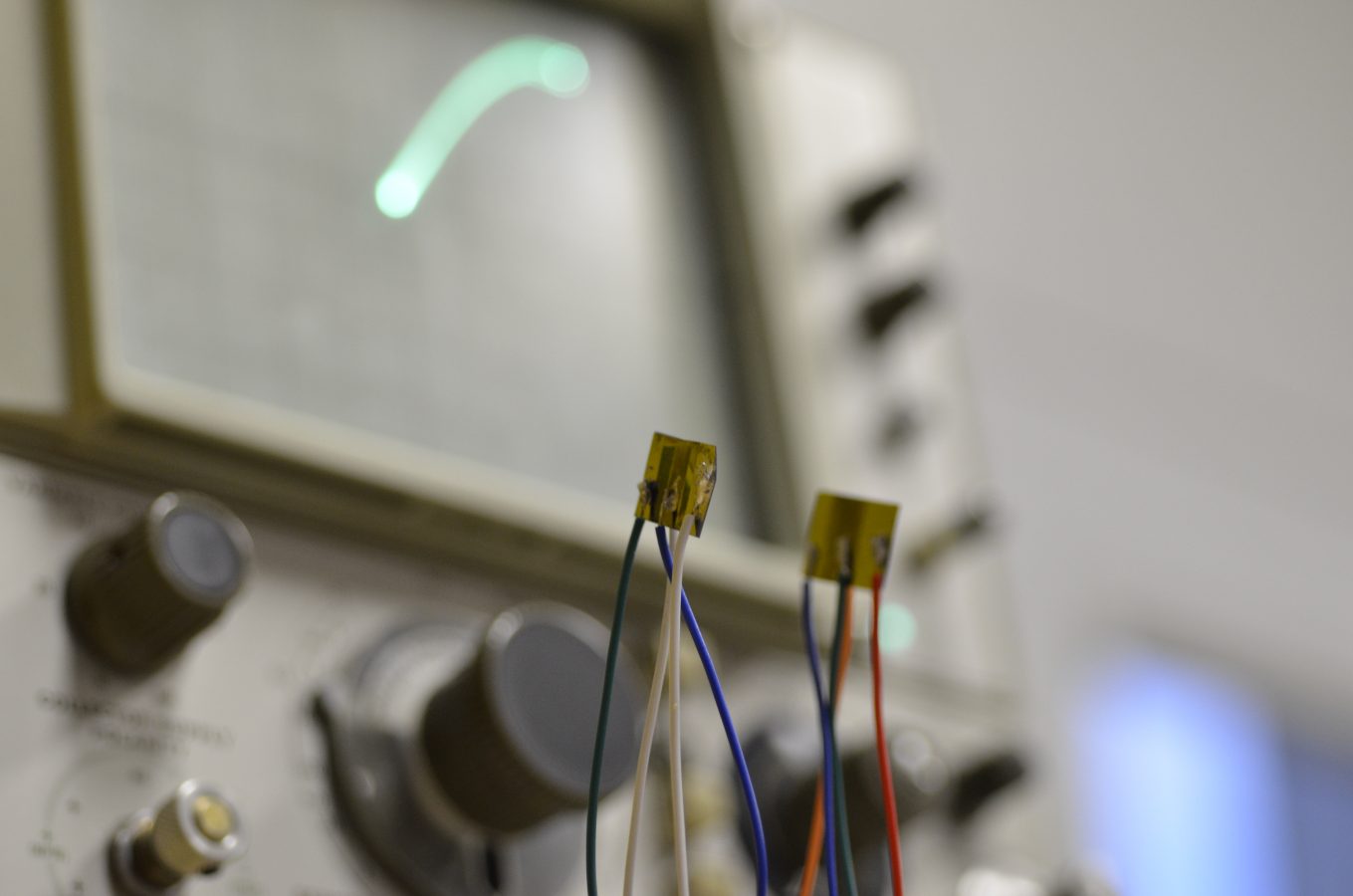
yes! I finally got wire bonded chips this summer. Wire bonding is an art in itself, but the resulting chips look so nice
 @Sam Zeloof Do you already have plans (in terms of target feature size and implemented circuitry) for the 'Z2'?
The wire bonder was graciously donated, but you can find them on ebay as well. getting the top metal layer (aluminum) to "stick" on the chip was a huge challenge, too
![]() @Sam Zeloof approximately how much have you spent on your whole setup?
@Sam Zeloof approximately how much have you spent on your whole setup?
 @Sam Zeloof how are bond wires 'stuck' on?
![]() ultrasonic welding?
ultrasonic welding?
@morgan there's at least 10 different ways
@Stefan Biereigel as far as circuitry, I was never interested much in making specific chips, but rather the processes. Although I do have some ideas for FPAA - like structures. As far as the feature size, the practical limit for chips at home (until someone makes a safe ion implanter) is 1 to 2um, which I am close to anyway. I would focus on changing the process, probably using polysilicon gates on the Z2 instead of aluminum
hmm, i mean 50um is still not bad. not super great for chips, but would be fine for doing traces for some simpler projects. certianly enough for a basic microelectrode array
@morgan many ways, my bonder used heat, pressure, and ultrasonic
@Sam Zeloof Dude. Lets build a better exposure unit. Are you up for it, or do you wanna hang around on pathetic 50um??
cool, a video I missed (and I reminder I hate the youtube suggestion system)
@thethoughtemporium for sure, but the good news with chips is that you can make them as big as you want. sure, it may be slower because of increased capacitance, but FET characteristics depend on the gate width to length ratio. so a linear scale-up still gives you good devices, within reason
@Sam Zeloof Building shit like that is the reason I moved into a maybe-tobe war zone
i looked at ion implantation a while back. not hard to build, it's just a linac and you can power it with a van de graff, but a nasty bugger to be around.
needs just as much shielding as a fusor
though no neutron shielding so it's technically easier. just some big sheets of lead
 dude, van de graff is so old-school, I'm sure David can give you a shiny Shenzhen high voltage transformer :-)
Yes for sure its doable, you only need ~30kv velocity to reasonably dope Si.
But the problem is in the dopant source, most of them are very very hazardous, phosphine, diborane, arsine
ya those... aren't pleasant to work with.
I thought about it for a while but never tried making one, but I would probably take the approach of "plasma immersion ion implantation" which has no ion mass selection (no linac, just a big chamber)
but isn't it just a few atoms? like 1:100 million
and would experiment putting small solid sources of dopant material (phosphorus, boron oxide) in the chamber and heating them to produce small and controllable amounts of dopant gas. Of course, the exhaust from the vacuum pump would be out the nearest window...
i've been playing around with some designs for direct ion writing. wanted to mod the magnetron to focus the plume to a beam and then move it around with some deflection lenses. no idea what sort of resolution you can get out of something like that though
who needs a mask when you can just print your traces directly! least that's the dream. probably won't get to try it for a while though
![]() See Applied science video on electron microscope for that.
See Applied science video on electron microscope for that.
![]() focusing the beam might me the hardest
focusing the beam might me the hardest
I have a green book somewhere on the theory of ion implantation, it mentions direct write doping with a technique like that. Ill dig up the title and send it later, its certainly possible but was abandoned in the industry for speed and resolution problems. Focusing a beam of positively charged things is so much harder than negatively, like electrons i think.
its a good idea, and would be so cool if you could mess with it.
![]() you also needs a lot of em shielding.
you also needs a lot of em shielding.
i figured as much. mostly just want to do it for the same reasons i do anything. seemed fun to mess around with XD
@Chris Gammell talks often about printing ICs on the amp hour, maybe he has some ideas how to do it?
for sure. I have some random plasma related experiments here, that may be of interest. http://sam.zeloof.xyz/category/plasma/ Looking forward to your direct chip writer...
what are you using as your rf source for that rf plasma?
10M ham radio or CB radio, 25W and sometimes with 200W LDMOS amplifier
anything will work, 1khz to 100mhz easily, as long as you have a matching network and more than a few watts
Hah, cool. Is that why you got your ham license? Or did that happen first?
![]() Can I use Tesla coil for that?
Can I use Tesla coil for that?
hmm interesting. i just used a desktop tesla coil as my rf source XD kinda worked and ingnited plasma easily but didn't really strike me as enough power to really do anything. i'll look into a ham transmitter
Actually had the ham license first, but this was a nice use for it!
![]() because the coupling between the two coils is weak.
because the coupling between the two coils is weak.
Discussions
Become a Hackaday.io Member
Create an account to leave a comment. Already have an account? Log In.