 Myself
-
R/C Transmitter (Tx) as a virtual joystick, no extra components
02/02/2022 at 22:37 • 5 commentstl;dr:
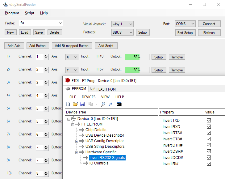
Use the pin-invert function on an FT232 to read an S.BUS stream into a PC without needing extra components to invert the signal. Thereby, take the S.BUS output of an R/C Tx/Rx and pipe it straight into vJoySerialFeeder which parses the packets and maps the values to a virtual joystick for flight-sim or any other use.
Background
If you want to practice "flying" without crashing your real model, you can use a simulator. The best sim practice comes from having your real Tx in your hands, so you can build reflexes with the same sticks and switches you'll be using later. So you want to connect the Tx to the computer somehow.
This should be pretty straightforward, as all modern R/C transmitters are computerized, so once the ADCs have done their thing reading the stick positions, all you need is to grab the data, right?
Riiiiiiiight.
More expensive transmitters have this function built in; just connect a USB cable and voila, it enumerates as.... something, perhaps a HID joystick? I don't know; I don't own one of those.
But there's a very simple way to do it, even with the very cheapest radio on the market.
First, some history.
I'm new to RC so researching this writeup has been a way of teaching myself some history. I've surely gotten some details wrong (comment below!), but in broad strokes, this is my understanding of how we got where we are:
Old-school R/C Tx: Producing a PPM pulse-train.
Very old (WWII-era) Radio Control schemes used multiple radio frequencies, or "channels", one per function. Each control stick or button was almost its own transmitter, with a corresponding pile of receiver channels on the model (or target drone, as the case may be).
Then (perhaps in the 60s or 70s?) someone figured out multiplexing: By connecting each stick to the transmitter in turn, all the control values could be encoded as pulses onto a single FM radio channel, round-robin style, many times per second. But the nomenclature of counting sticks as "channels" had stuck, and has been a misnomer ever since.
The way this worked isn't too important but it's interesting: Take the ubiquitous 555 timer, and connect it as a one-shot. Its pulse width is determined by a resistor and a capacitor. Variable caps are expensive and awkward, but variable resistors are cheap and easy! So by using a fixed cap, and measuring the time it takes the timer to cycle (the width of the pulse), you can determine the (relative) position of the resistor.
Side note, the PC Joystick!
This, incidentally, is exactly how the original PC game (joystick) port worked:
http://mysite.du.edu/~etuttle/electron/elect57.htm
and https://www.epanorama.net/documents/joystick/pc_joystick.html
And the Rx: Slices that up and hands each pulse to a servo.
On the air (or within the baseband multiplexed stream), the pulses representing each control are all run one after another, and the position of each pulse encodes its value, hence the name Concatenated Pulse Position Modulation.
When it's sliced up and each pulse goes to its individual servo, there's just one pulse, and its width represents the value, so in that form it's called Pulse Width Modulation.
https://sourceforge.net/p/arduinorclib/wiki/PPM%20Signal/
Some vintage Tx/Rx schematics here: https://norcim-rc.club/Radio9a.htm
The "trainer port" and the "buddy box", standardizing CPPM.
So, radio-wise, the modulated carrier is pretty straightforward. But it never exists as a baseband signal outside the Tx or Rx. Or does it?
Prior to PCs that could run flight-sims, the way to train as a new pilot was a "buddy box", a way for two pilots to hold two controllers, but only one was transmitting to the model. The trainee's Tx (with its actual radio turned off) would output its CPPM signal via a jack on the back of the unit, and the trainer's Tx would take that in and use...
Read more »
My Pages
 Oskar Weigl
 Shah Selbe
Share this profile
ShareBits

Jasmine Brackett
wrote 07/09/2014 at 00:06
•
point
Come to the Hackaday Detroit Meetup this Friday http://hackaday.io/event/1823-Detroit-Meetup. Tell your hacking friends.