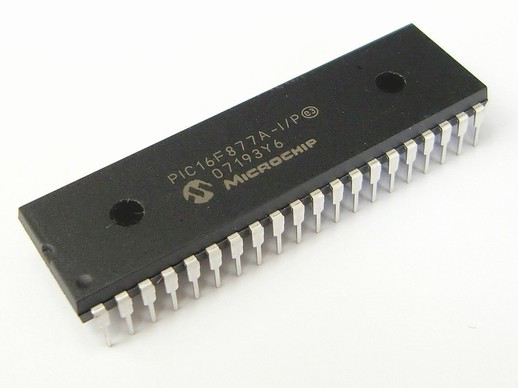
PIC16F877a is a low-power microcontroller device in the 16-pin family of PIC® microcontrollers. It features an enhanced instruction set, greater program space and data memory space than its predecessor, and on-chip peripherals to simplify system design–all in a package requiring only three external components.
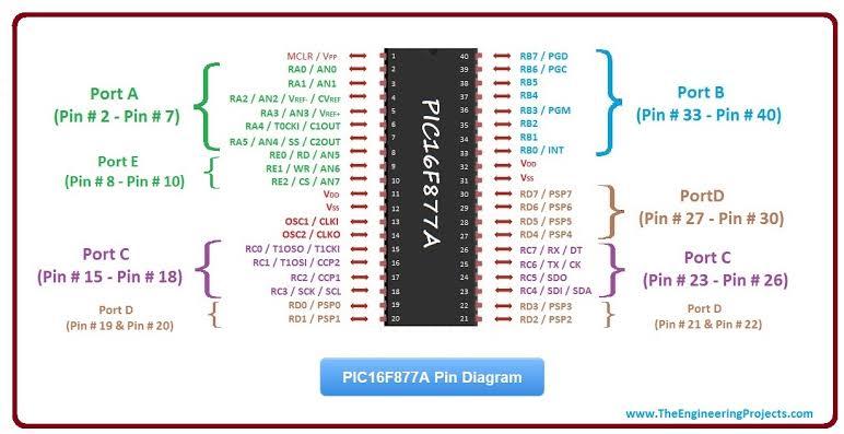
PIC16F877a microcontroller has 8 KB of internal EEPROM, 512 bytes of RAM, and 4 KB of flash memory. It provides 14 digital I/O pins, 8 analog input pins, a UART interface for serial communication, and a full-duplex asynchronous hardware serial interface that supports RS-485. The PIC16F877a is an improved version from PIC16F876A with an extended number of input/output lines.
PIC16F877a is an 8-bit microcontroller but has a 16-bit program counter, 16-bit stack pointer, and 16-bit data pointers which makes it look like a 16- bit machine. Approximately 20% faster than PIC16F876A, PIC16F877a has more input/output ports with improved peripheral features.
PIC16F877a is available in the 44 pin TQFP package. It can be programmed using an MPSIM simulator or MPLAB IDE. The instruction set of PIC16F877a is similar to PIC16C84 but without some special instructions intended for LCD modules. The low-power features of PIC16F877a include:
Unlike the other modules, the instructions in this module are executed as fast as possible. To keep program execution time as short as possible, instructions associated with EEPROM and RAM accesses have been given a higher priority over those associated with input/output ports. This results in a maximum instruction execution time of 4 cycles.
The first part of an assembly program is always a RESET instruction which initializes the microcontroller by clearing all the registers and initializing memory pointers.
On power-up, PIC16F877a clears all the I/O ports and memory locations. It then jumps to location 00FFh in internal program memory from where it picks up the first instruction. The following code shows the reset sequence in the case of PIC16F877a:
The assembler directives are used for special purposes in assembly language programs. These directives are inserted into the program by writing a comment which starts with an asterisk (*) and a letter for each directive, with spaces separating words.
What are some of the enhancements to the PIC16F877a processor?
PIC16F877a is a third-generation PIC microcontroller that offers advantages in speed, space, and power consumption over its predecessors. Designers will enjoy the enhanced instruction set–there are more than 30 new features provided for this chip. For example, new instructions allow programmers to access the internal RAM without accessing external memory, and new bit manipulations can be used to "byte-shift" or "bitwise OR" data while shifting data only one bit at a time. PGER capability has been enhanced with additional bit manipulation instructions that also operate on bytes or words rather than bits.
What peripheral functions are included on the PIC16F877a?
The PIC16F877a has a full complement of built-in peripherals, including a 12-bit analog-to-digital converter (ADC), 5-bit digital to analog converter (DAC), real-time clock (RTC), two hardware timers, and a watchdog timer. Programmable features such as input capture, output compare a serial port, 8-to-16 converter, real-time interrupt and gate array, 10-bit digital comparator, and timer/counter are also included.

The PIC16F877a processor has an on-chip memory consisting of internal program memory (Code), data memory (Data), and EEPROM. Internal program memory is only readable by the PIC target machine. The program structures located in the Data memory must be written to EEPROM before they can be read by the target machine. The data structures placed in the internal program memory are located at addresses 0000h to 0004h; all other data structures are located at addresses 000Fh to 00FFh. All registers within the chip consist of 16 bits.
How do I wire my PIC16F877a?
Wiring a PIC is done by placing the device and its support components on a circuit board and then connecting the device to the power supply with input and output wires. This includes connection to capacitors, resistors, LEDs, and switches. By using this method with the proper support components, such as decoupling capacitors, voltage regulators or linear regulators, and filter capacitors, designers can be assured of the successful operation of their products.
How can I program my PIC16F877a?
The programming for the PIC16F877a is done by placing the device in an in-circuit emulator or a PC-based programmer. The programmer is connected to the target machine through the serial port. On operating systems like Windows, Mac OSX, and Linux, programming can be done using MPLAB IDE or ISSCRIPT. Both these programming methods are equipped with an in-circuit emulator that allows designers to program their microcontroller without having physical access to it. This is done by connecting the microcontroller and its support components on a circuit board and then connecting the device to the power supply with input and output wires.
What are some extra accessories available for the PIC16F877a?
There are several extra accessories available for the microcontroller. One of these is an onboard camera kit designed specifically to take pictures of the programmed microcontroller. Other accessories include a hex socket board that slides onto two headers located on the bottom of the 16F877A and a 32-pin QFP adapter that slides into place on top of the device and allows it to be connected to standard breadboards or direct connect sockets for simple prototyping.
What is a unique feature of the PIC16F877a?
The PIC16F877a has a flexible pin-out that makes it easier to implement in small packages. The PIC16F877a can be programmed via an In-Circuit Emulator (ICE) without having physical access to the device. In addition, it has an onboard Camera Kit designed specifically to take pictures of the microcontroller as well as a 32-pin QFP adapter that allows easy connection to prototyping boards and breadboards for quick prototyping.
What are two key issues regarding the PIC16F877a?
Two key issues regarding this device are its reduced memory requirement and reduced power consumption. With the reduced memory requirement, designers can save drastically on development costs. With the reduced power consumption, designers can save on battery or power supply requirements in their systems.
What is the current status of the PIC16F877a?
The latest addition to the PIC family, this microcontroller is now made by Microchip Technology. The design goal was to maximize functionality and performance with an emphasis on ease of use by providing a complete set of peripherals, a high-level programming interface, and a wide range of features. The result was a PIC that provides greater functionality, improved performance, and takes up less space.
Discussions
Become a Hackaday.io Member
Create an account to leave a comment. Already have an account? Log In.