 Ken Yap
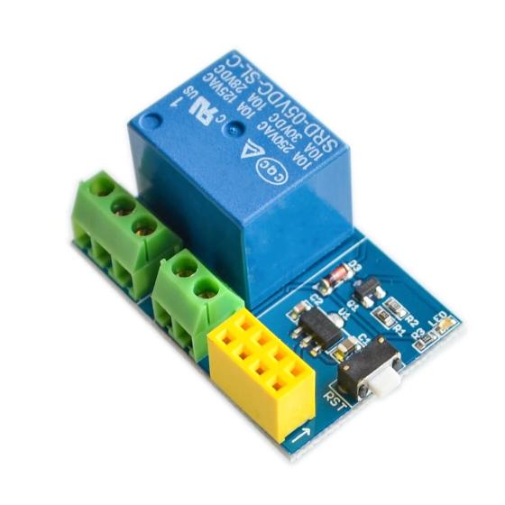
I bought a relay module and the matching ESP8266-01 WiFi module for a couple of bucks (bargain!), in order to experiment with remote control. In particular I'm thinking of fitting one into an amplifier for remote turn-on. The module is quite small, that photo is larger than life size. It's about the size of a matchbox and perhaps twice as high. The ESP8266-01 fits onto the 8 pin yellow socket in the picture. These are my notes on getting it to work. I will augment this page as I encounter and solve issues.
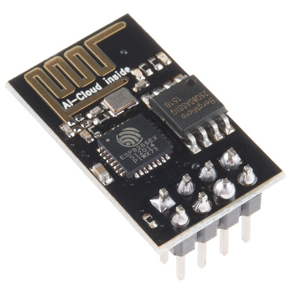
Sparkfun Electronics, ESP-01, CC BY 2.0
A search for ESP8266-01 will get you quite a few instruction pages. Usually they suggest you start by connecting a serial terminal on an Arduino to it. You could also use a FDTI adaptor. I came across these issues:
Diagrams show that you have to take the EN pin high (3.3V) to allow it to work. But the RST pin must also be taken high or the module may not respond. Later on you should make provision to ground GPIO-0 to flash programs if that's what you want to do.
Beware of "smart left and right quotes" on web pages if you copy and paste commands, in particular the command to register with an AP, giving the SSID and password. You must use the ASCII double quote.
In one Fritzing diagram, hosted by the Arduino site no less, a 5V to 3.3V regulator is shown on the breadboard you'll need to expand some connections like 3V3 and GND. I'm not sure why; the Arduino board, at least the Uno, already has a 5V to 3.3V regulator.
I came across one article discussing ways to expand GPIO. One way is to use an I2C extender. Besides GPIO-0 and 1, Rx and Tx could be used for a total of 4. But such measures are probably unnecessary nowadays; buy a later ESP8266 or ESP32 module with far more I/O pins for not much more money.
Last edited 2021-12-08
Discussions
Become a Hackaday.io Member
Create an account to leave a comment. Already have an account? Log In.