 Myself
tl;dr:
Use the pin-invert function on an FT232 to read an S.BUS stream into a PC without needing extra components to invert the signal. Thereby, take the S.BUS output of an R/C Tx/Rx and pipe it straight into vJoySerialFeeder which parses the packets and maps the values to a virtual joystick for flight-sim or any other use.
Background
If you want to practice "flying" without crashing your real model, you can use a simulator. The best sim practice comes from having your real Tx in your hands, so you can build reflexes with the same sticks and switches you'll be using later. So you want to connect the Tx to the computer somehow.
This should be pretty straightforward, as all modern R/C transmitters are computerized, so once the ADCs have done their thing reading the stick positions, all you need is to grab the data, right?
Riiiiiiiight.
More expensive transmitters have this function built in; just connect a USB cable and voila, it enumerates as.... something, perhaps a HID joystick? I don't know; I don't own one of those.
But there's a very simple way to do it, even with the very cheapest radio on the market.
First, some history.
I'm new to RC so researching this writeup has been a way of teaching myself some history. I've surely gotten some details wrong (comment below!), but in broad strokes, this is my understanding of how we got where we are:
Old-school R/C Tx: Producing a PPM pulse-train.
Very old (WWII-era) Radio Control schemes used multiple radio frequencies, or "channels", one per function. Each control stick or button was almost its own transmitter, with a corresponding pile of receiver channels on the model (or target drone, as the case may be).
Then (perhaps in the 60s or 70s?) someone figured out multiplexing: By connecting each stick to the transmitter in turn, all the control values could be encoded as pulses onto a single FM radio channel, round-robin style, many times per second. But the nomenclature of counting sticks as "channels" had stuck, and has been a misnomer ever since.
The way this worked isn't too important but it's interesting: Take the ubiquitous 555 timer, and connect it as a one-shot. Its pulse width is determined by a resistor and a capacitor. Variable caps are expensive and awkward, but variable resistors are cheap and easy! So by using a fixed cap, and measuring the time it takes the timer to cycle (the width of the pulse), you can determine the (relative) position of the resistor.
Side note, the PC Joystick!
This, incidentally, is exactly how the original PC game (joystick) port worked:
http://mysite.du.edu/~etuttle/electron/elect57.htm
and https://www.epanorama.net/documents/joystick/pc_joystick.html
And the Rx: Slices that up and hands each pulse to a servo.
On the air (or within the baseband multiplexed stream), the pulses representing each control are all run one after another, and the position of each pulse encodes its value, hence the name Concatenated Pulse Position Modulation.
When it's sliced up and each pulse goes to its individual servo, there's just one pulse, and its width represents the value, so in that form it's called Pulse Width Modulation.
https://sourceforge.net/p/arduinorclib/wiki/PPM%20Signal/
Some vintage Tx/Rx schematics here: https://norcim-rc.club/Radio9a.htm
The "trainer port" and the "buddy box", standardizing CPPM.
So, radio-wise, the modulated carrier is pretty straightforward. But it never exists as a baseband signal outside the Tx or Rx. Or does it?
Prior to PCs that could run flight-sims, the way to train as a new pilot was a "buddy box", a way for two pilots to hold two controllers, but only one was transmitting to the model. The trainee's Tx (with its actual radio turned off) would output its CPPM signal via a jack on the back of the unit, and the trainer's Tx would take that in and use it to modulate the RF being transmitted by the trainer's radio. If the trainee got the plane into a pickle, at the flick of a switch, the trainer could take over, with the trainer's stick positions being transmitted instead.
This forced the standardization of the CPPM signal level, voltages, and pulse-train order, and even a few standard connectors emerged. This is still called a "trainer port", even though today the trainer is usually a simulator, not a friend. (More's the pity!)
There are numerous USB dongles that take the CPPM stream from a trainer port, and turn it into some sort of input device, presumably a USB HID joystick, though documentation is obnoxiously poor and everyone wants to sell you their dongle instead of just telling you what properties to look for when selecting a compatible one. There are a couple DIY projects to do the same thing. I tried one Arduino sketch that acquires the PPM pulses and maps them to the axes of a USB HID joystick using the vUSB framework. Very cool in concept, but the values jittered all over the place, likely because the Arduino hardware lacks a dedicated timer capture peripheral.
Modern R/C Tx: Digital packets doing the same thing.
Today, of course, the stick and switch positions are sampled by an ADC and formatted into a digital data packet, with such niceties as unit IDs and checksums so multiple models can coexist (without juggling frequency-specific crystals like the old days) and then transmitted, usually as a spread-spectrum signal somewhere in 2.4GHz, which allows smaller antennas.
That signal between the Tx and Rx is known as the "air protocol", and may be brand-specific, but some standards exist and some polyglot Tx's can talk to many different Rx's:
https://oscarliang.com/rc-protocols/
Modern Rx: Turns out CPPM is a handy way to connect Rx-FC.
The receiver, then, receives the packet, validates the checksum, and twiddles its output pins to make PWM pulses for the servos connected to it. As far as the servos are concerned, it's identical to the old FM style; the transport is immaterial.
And that's great if you're controlling a bunch of discrete servos connected directly to throttle, rudder, ailerons, elevator, etc. Many planes use exactly this setup today, unchanged from the 70s.
But what if, as in the case of a multicopter which isn't inherently stable, you have a flight controller onboard? Its accelerometer and gyroscopes are actually directing the motors, merely taking suggestions from the human via the R/C link. It's sort of awkward to take a single RF signal, demux its CPPM to a bunch of individual PWM signals, connect a whole bunch of discrete signal wires between the Rx and the FC, dedicate a bunch of input pins to those signals, reacquire the pulse width on each pin, and use them as numbers in a piece of software controlling the craft.
Why not have the Rx output the straight CPPM stream, and use a single pin on the FC to capture the pulse widths? The order is specified, the voltages are standard.... And this is exactly how a great many multicopters work today. Most Rx units can repurpose a servo pin to output a CPPM stream, and every autopilot firmware understands a CPPM input and lets you map the channels to the appropriate functions. It saves a bunch of pins, wires, and interrupt load. CPPM thus became the first common "receiver protocol", which is the term used for communication between the Rx and FC using something other than discrete-wire PWM servo signals.
And naturally, you can pipe the Rx's CPPM stream into your USB dongle too, instead of using the Tx's trainer port, and your Tx becomes a wireless gamepad. How fancy!
Modern data: But since it's digital already, let's use a UART instead. Enter S.BUS.
But that's still not as efficient as it could be. Using timer peripherals to output pulse widths, and using more timer-capture peripherals to acquire them, adds uncertainty and jitter and complexity and processor interrupt load. Why not define a receiver protocol that just spits the packets out over UART between the Rx and the FC?
Turns out a few folks had the same idea, and there are a few conflicting standards for it! Le sigh. But S.BUS by Futaba seems to be the most common, and it's very simple:
https://github.com/uzh-rpg/rpg_quadrotor_control/wiki/SBUS-Protocol
Wherein our hero discovers vJoySerialFeeder.
So, using an R/C Tx as a PC input device is great, and there's software for it already. vJoySerialFeeder can read a bunch of protocols including S.BUS, and map the signals to virtual joystick axes in the vJoy framework. All you have to do is get it into the PC somehow.
https://github.com/Cleric-K/vJoySerialFeeder
I'm not sure whether there are any Tx's that output S.BUS over their trainer port, but plenty of Rx's can definitely output S.BUS on a repurposed servo pin. The wireless gamepad (with no CPPM jitter) can be yours, for the cost of one USB UART and a little hassle and some discrete components! Here's why:
Turns out S.BUS is a contrarian little pain in the butt.
S.BUS is a great concept, but two minor details make it awkward to implement in practice:
First, the baud rate, of 100,000 baud. That's easy to generate from decimal clock crystals, but most RS232-type UARTs are equipped multiple-of-3 crystals and may not understand this baud rate. In practice, most UARTs have pretty flexible clock divisors, and if the driver will pass an odd request to the chip, it can get close enough and it's not an issue.
(Also, the data format is 8 data bits, even parity, 2 stop bits. Extremely non-standard but still within what most UARTs support. When's the last time you saw serial data that wasn't 8N1?)
Second, the signal is inverted compared to how most TTL-level UARTs work. RS232-standard signals are inverted, but at high voltage, with -12v representing a 1, and +12v a 0. Most TTL UARTs use 3.3v or 5v for 1, and 0v for a 0. But S.BUS uses 0v for a 1, and 3.3v for a 0.
Sure, sure, it only takes one transistor and two resistors to make a signal inverter. But in practice that's a bit awkward, and countless words on RC forums have been spent on finding ways to grab the non-inverted signal before its output transistor, etc. And many flight controllers already have circuitry built right in to accommodate this.
Perhaps there's an easier way...
FTDI already thought of this.
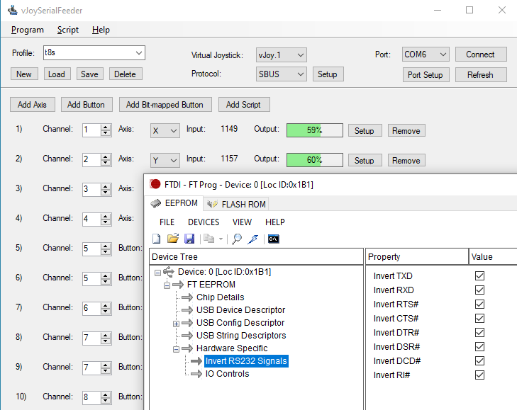
Inverting a signal is really simple, so adding it to the USB-UART chip doesn't add much complexity. Add some config bits in the EEPROM and let the user twiddle them with the FT-PROG utility, and you eliminate a lot of glue logic in certain applications, which makes the FT232 more valuable in practice. Seems like a perfect fit for working with S.BUS!
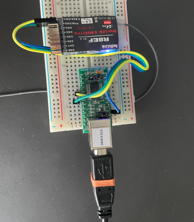
I scoured the internet for this and couldn't find anyone using it in this application. By setting the receive data line to be inverted, it's possible to pipe the S.BUS stream from the Rx straight into the FT232, opened by vJoySerialFeeder, with no extra components.
(Word to the wise: Once you've changed this on one of your FT232's, label it clearly! No end of frustration awaits, if the inverted unit gets mixed into the general population of UART adapters in your lab.)
Sometimes it really is that simple.
Discussions
Become a Hackaday.io Member
Create an account to leave a comment. Already have an account? Log In.
Hey, this was a great article, thanks.
I have a project in mind that could use this.
I do have a couple of questions though. You briefly mentioned modifying the EEPROM using FT-PROG utility, to get SBUS to work.
Would you mind expanding on this as I have no idea how to achieve this?
Regards
Kobus
Are you sure? yes | no
The first screenshot shows the settings you need to change in FT-PROG. That's all there is to it.
In order to use this, you need an adapter with a real FTDI chip, which might be somewhat tricky as they're frequently counterfeit.
Are you sure? yes | no
Thanks for the info. I've ordered one from FTDI themselves. Will see how I manage once it arrives.
K
Are you sure? yes | no
Hi M.
OK. I received my FT232 card and was able to update the EEPROM without any issues - straight forward as you mentioned.
I do have vJoy installed but cannot get SerialFeeder to run. I've downloaded the code from GIT, and also VB. However, I have NO idea on how to get the GIT repo in such a format to install or run on Windows.
K
Are you sure? yes | no
good
Are you sure? yes | no