 helge
helgeI bought a device that harbors a Mini ITX mainboard (Intel D410PT(B)). It also had a power supply failure, so we're left wondering whether that in turn damaged the mainboard as well. First off, this is a no-fix, but maybe you'll enjoy the story of the journey.
Initial presentation:
ATX power supply is completely dead.
It's a Seventeam ST-250UAG-05E, a regular 1U server PSU. When connecting to mains and bridging PS_ON# to GND, it should turn on, but no 5V_STB is present either.
It's got active PFC creating a 380V intermediate DC rail, so there are > 400V transients across its 20N60 MOSFET to be expected (capacitor ESL and commutation loop causes some overshoot. Can you see it?
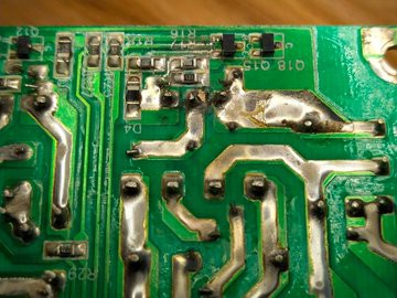
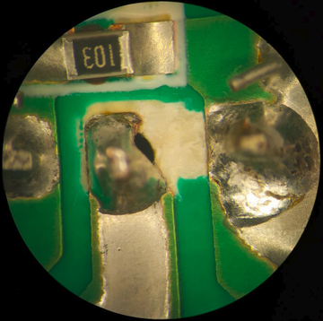
Here's a closer shot:
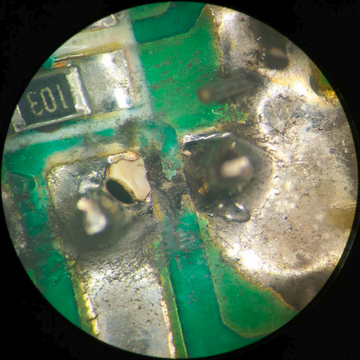
It should be noted that in the pictures above, the worst of the contamination (paper and toner dust, as this was an office scanner) has already been vacuumed out and brushed off while vacuuming. The charred remains and light metal deposition over the "R17" silkscreen label, along with the fancy golden alloy that formed around the arced spot tells what happened here. The clearance between those two traces really is overly optimistic and inadequate for adherent pollution.
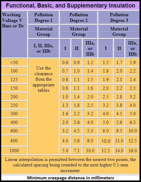
As per https://www.protoexpress.com/blog/importance-pcb-line-spacing-creepage-clearance/ , IEC60947-1
Pollution degree 2 would apply: "Mostly, there is non-conductive pollution. However, there is a possibility of temporary conductive pollution, which is caused due to the condensation. Laboratory area is one of the examples of pollution degree 2."
Let's see what 400V working voltage and pollution degree 2 call for:
1) staggered pins can directly increase clearance, albeit at increased assembly effort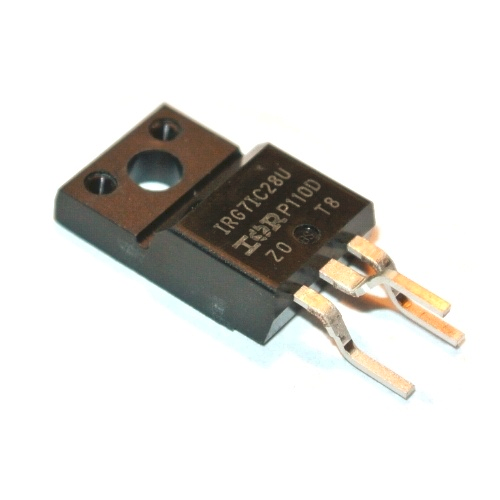
3) the best result is achieved by combining staggered pinout and isolation slot milling.
The PSU needs to be fixed.
It ain't fixin' itself. OK, that's not completely true, maybe the ablation caused by the arcing did fix it somewhat, but upon measurement it turns out that the MOSFET is OK, but the 5A fuse is blown.
Course Of Action:
- clean and abrade arc damaged on PCB (heat-affected PCB material can become a future source of arcing and recurring failure)
- trim traces with exacto knife
- reflow with some flux
- thorough cleaning with ethanol or mineral spirits to strip flux residues
- application of Plastik 70 conformal coating (acrylic resin)
- test*
This restored the PSU and allowed the machine to be powered when adding a wire to short PS_ON# to GND. The mainboard however would not start at this point when merely shorting the PWR button pins on FP_HDR.
(*) Earlier I mentioned 380V for the PFC stage. As one doesn't get proper technical documentation these days, this voltage was measured after fixing the PCB and fuse. I've got a 250V lab power supply set to a 50 or 100 mA limit to keep the risk of electric shock and device damage limited. it also allows gradually ramping up the input voltage under a current limit. Most switch-mode power supplies also run off DC without issues, and start at 85 - 100V AC with universal input, so they should accept 150-250V DC as well. 100 mA aren't particularly safe and the floating output means there is no RCD saving the day - maybe a future lab upgrade might be a dead man switch that cuts the interlock after 10 seconds without a button press?
Further reading: https://www.powersystemsdesign.com/articles/safety-vs-performance/36/10909
The State Of The Mainboard
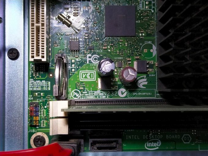
It has a green power indicator LED which lights when the now-fixed PSU is switched on, 5V_STB is 5.1V.
As it turned out, the mainboard wouldn't just start the power supply when cold-started, but started running with the bridge inserted into power connector.
Front panel header (FP_HDR, bottom left) has power and reset button pins which can be shorted. For the most part, turning off power, removing the BIOS battery, re-inserting and cold-starting reliably managed to get the board to run once.
Initially, it was sufficient to start the board once via battery swap, but it would not start again after the PSU had been disconnected / hard switched off. From what it looks like now, this may be due to a damaged voltage regulator or monitor, or a faulty BIOS configuration.
Visually, the board seems to be OK, but voltage rails and odd things like crystals haven't been validated.
With the board starting (sort-of), it's apparent that the BIOS is password protected (and it's not "sysadm" or any other password mentioned in the product's "administrator's guide", because according to Kodak, the admin is just another guest). In the picture above, the CMOS_CLR jumper is not present and the pull-up resistor footprint below is not populated.
I tried to achieve something here by hooking up a DMM with a 470R shunt resistor over its terminals and using fine needle probe tips connected to the DMM to get it to reset. The DMM comes in handy as it gives a feedback of whether the resistor makes contact, and whether the needles are actually on the pads (there will be some current flowing and hence a voltage drop). Turns out that this model does not use that header for CMOS clearing, but uses a jumper elsewhere on the PCB:
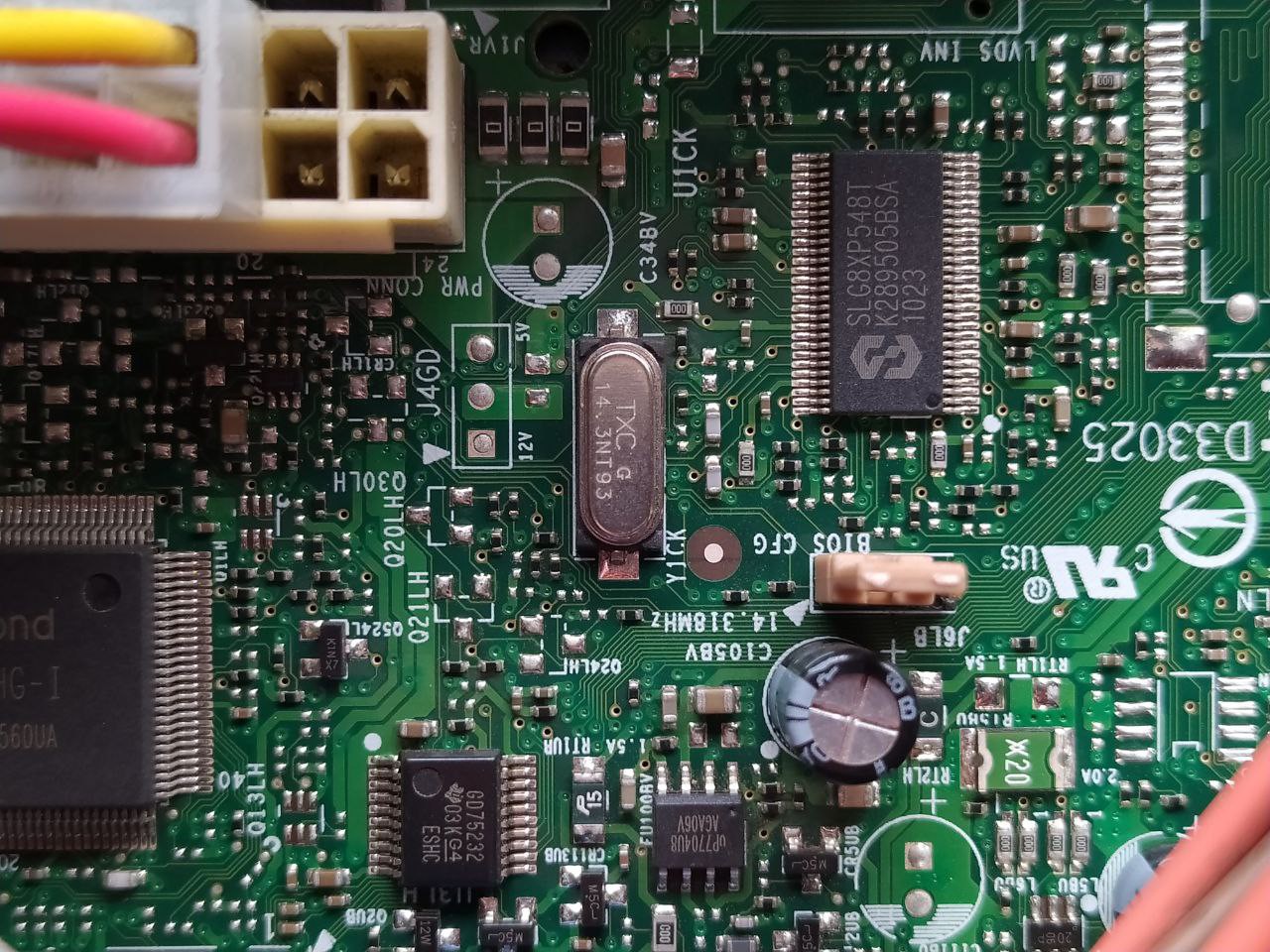
It's called "BIOS_CFG" and when powering off, swapping the battery and moving the jumper to the 2-3 position, one can enter the BIOS and is asked whether it should be reset. This successfully clears the password. The jumper needs to be reset to its 1-2 position afterwards.
The log still shows a CMOS Checksum Failure error and does so every time. The errors can be cleared and are not reported after reboot, so it's unclear whether they are a real issue. People sometimes seem have cases where this error is recurrent (see https://community.intel.com/t5/Intel-Desktop-Boards/CMOS-Checksum-error/td-p/326399).
Maybe a BIOS update does the trick? Intel no longer supports the board and has given up on maintaining documentation and downloads. They can currently be found at
https://www.helpdrivers.com/motherboards/Intel/Motherboard_D4_xx_Series/Motherboard_D410PT/
There is also a .BIO file to be used on a USB drive present before boot (otherwise it will not be recognized), but the issue that after resetting the BIOS, it would just turn off and not turn on again led me to pursue the bootable-drive updater utility route next.
A small USB thumb drive is formatted (https://kb.iu.edu/d/bccm), set up as a bootable device (https://rufus.ie/) and the BIOS update for version 0524 (previously 0158) is copied onto the drive.
Rufus will fail when the fs is NTFS or exFAT. The necessary commands for an interactive diskpart session are:
- In the Start menu, type cmd, and then click the entry for the cmd program.
- At the command prompt, enter diskpart (you might have to approve this operation as an administrator). The prompt line should now display "DISKPART".
- Enter list disk.
- Enter select disk X, where X is the number of your selected disk.
- Enter clean.
- Enter create partition primary.
- Enter select partition 1.
- Enter active.
- Enter format fs=fat.
- Enter assign.
- Enter exit.
Afterwards, the drive can be initalized with MS-DOS and the BIOS update archive contents containing IFLASH2 can be added.
A keyboard and the thumb drive need to be plugged into the mainboard USB jacks without additional hubs.
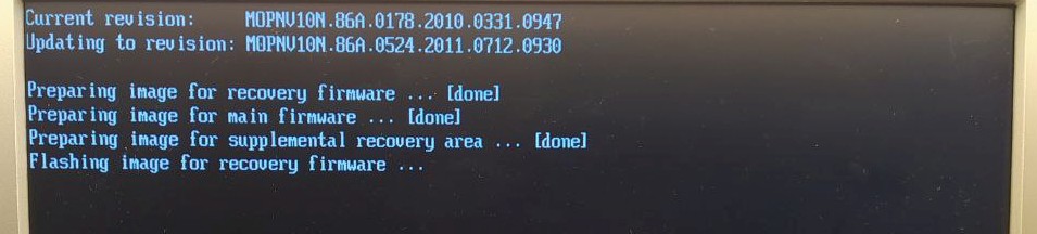
IFLASH2 /p MO0524P.BIO
works, but adding /nr results in a "BIOS update without reboot not supported" error. At that point the board would just turn off instead of rebooting. Adding the PS_ON# jumper again allowed the board to make it through reset and indeed perform the update:
Finally, pressing F9 and resetting the newly updated BIOS should do the trick then?
At this point, the initial capability to turn on upon PWR button presses seemed to have been recovered.
After a final test with switching off the PSU and turning it on again though, we're back to almost square one. The board won't start. What was learned: how to remove the BIOS password protection, and how to update the BIOS despite the board not wanting to stay powered up.
Conclusions.
- PCB pollution degrees are a thing.
- if you want "clearance is clearance" to be true, why not explore CNC machining a bit more.
- Know when you've lost, but don't give up before that.
- Mourn the wasted time, but do not feel shame.
- You now have a bootable DOS thumb drive.
Edit: After sleeping over it for another night, I removed the BIOS battery. We'll have to live with one-time error messages about battery and CMOS failure, but the board will be able to power on. This minimizes momentary expenditures, and what's more, the whole unit has yet to be set up and prove to work. No point in buying a replacement mainboard for a device that has other issues going on as well.
Discussions
Become a Hackaday.io Member
Create an account to leave a comment. Already have an account? Log In.
Nice detective story. It's a good feeling when you have a win like this.
Are you sure? yes | no
Thank you. It's perhaps a case of "you don't get what you want, but what you need" - in that sense it was a nice exercise in persistence. One also keeps asking oneself how better to probe and attack a problem without immediately breaking things.
Perhaps someone else stumbles upon this, too. Search engines say I'm not the only one that has the "doesn't turn on anymore" issue, so this would be the right time to let it go and get a replacement mainboard :)
Are you sure? yes | no