 micl
miclI work with PCB's a lot, directly in the creation process.
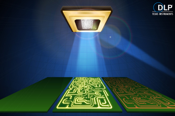
Simply etching out the copper (I am usually using a LPKF mill) is generally not enough to make the board usable to the general public (or pleasant for yourself). Soldermask is generally applied over the copper (Solder-mask over copper, or SMOC) which is done via application of a thin paint that is cured selectively with a UV positive or negative image.
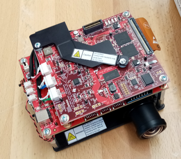
I recently picked up one of these. It's going to help me make better PCB's from scratch by using MEMS. Specifically, some optics, some LED's, and a Digital Micromirror Array (DMD). By replacing one (1) LED, I can cure soldermask using nothing more than the HDMI output from my computer.
 DMD displays aren't new technology (for some reason, I believed they were). They're some of the (possibly the) oldest MEMS category silicon devices that exist.
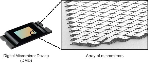
They contain millions of tiny reflective squares that actuate in some particular directions by about 12 degrees. When you shine light onto them, if you selectively choose which mirrors to reflect light towards somewhere else, you can create a pixel defined image
This opens up an entire world of interesting possible optics applications. They're found in everything from alternate-reality glasses to your standard highschool-teacher-is-away-lets-watch-movies (too specific?) projectors.
The most basic application is just projecting some video output onto a wall, to watch movies or something. Usually it's implemented in a system like this:
 The development kit I purchased does not work like this. However, the diagram is useful for understanding how it works. A light source is emitted, it is focused onto the DMD device, and then is reflected towards an output projection lens.
 My evaluation kit replaces the colour wheel, with 3 individual LED light sources (red, green, blue) instead of a white laser array.
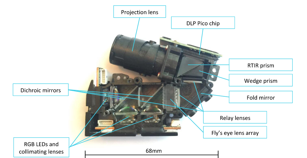
The omission of the colour wheel substantially improves the performance of the system when your intent is to reflect as much of the light out the lens with as little loss as possible. This also means that I can replace one of the colour channels with light of another wavelength. For example, ultraviolet light -- so long as I meet the maximum ratings to comply with my device warranty (there's a specific W/cm^2 limit).
Purchasing an OTS solution here is pretty much the easiest way forward. You know that the development kit will have reasonably decent optics if you buy a middle-of-the-line model. It's machined and black anodized aluminium, and I cannot see any noticeable lens imperfections at a glance.
By purchasing the kit, it also means that I do not have to deal with developing a board to drive the DMD and projection engine. The LED's are each on their own individual boards, I just swap one out.
 The red LED passes through the least number of mirrors and lenses, and is therefore the least alterted light source (because it's a lower wavelength than green or blue, this design choice makes sense). Replacing it with a UV source means that I can maximize the output.
 The board is controlled by a zynq FPGA (xcz7020) and a TI microcontroller (MSP430). I can program these to adjust for LED parameters (voltage, drive strength, drive frequency).
I'm putting it to the side for now, but the next update on this topic will go over my first attempts at getting this projector to function as a positive photoresist UV curing system.
Discussions
Become a Hackaday.io Member
Create an account to leave a comment. Already have an account? Log In.
Any news from your project ? I'm very interested also...
Are you sure? yes | no
I developed the DMD devices as an Air Force Officer/Scientist (Physicist) with Texas Instruments in the Mid 90s. Hope you are successful.
Iron-Man
Are you sure? yes | no