 danjovic
I have assembled a prototype for the shinobi tap and during the tests I came across a tricky problem: One of the famiclone controllers worked erratically when connected on position 1. All wiring was checked twice and it was OK.
Exchanged the port where the interface was connected and same results. Exchanged data wires from controllers 1 and 2 and same results.
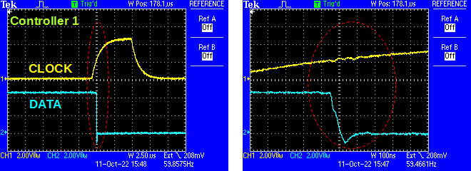
Observing the waveform on a scope it was noticed that the voltage briefly dropped when a button was pressed, instead of keeping low until the next clock pulse.
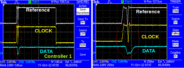
A closer observation on the waveform at the moment of a button press revealed the culprit: A short surge that happens when the voltage drops at the output and makes the clock ring. The same effect occurs with both controllers but only one of interpreted this as an extra clock.
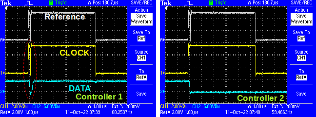
On the other ports the ringing is barely noticed.
I was suspecting that the ringing was happening only on port 1 because of the proximity with a low impedance source (the electrolytic capacitor at the input). but some tests I have done later proved I was wrong.
I have tried without success:
- Added some capacitance to the Vcc line.
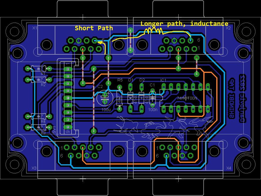
- Replace the VCC jumper wire with an inductor
- Added a 100 Ohms termination resistor on the pin 4 of the Port 1 (CLOCK)
- Add some resistance in series with the CLOCK out pin (3) of the HCT00
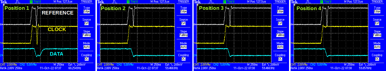
Later I noticed the the other controller (that works despite the ringing) produces the ringing when connected to ports 1 and 2 but not when connected to 3 and 4.
Another thing I have noticed is that when more than one controller had the same button pressed, the ringing was deeper and last a little longer.
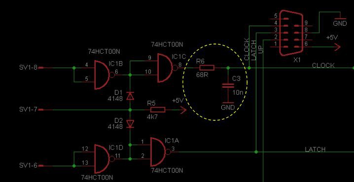
Added a 100nf capacitor (value picked at random ) between CLOCK and the ground. This time the ringing disappear and the circuit worked despite the clock signals turned into triangles.
Then I have analyzed again the width of the clock pulse and the duration of the ringing to determine an RC constant to be added between the HC00 and the CLOCK line. The Clock signal takes 6us and the surge around 250ns.
Then I pick a 68 Ohm resistor and a 10nf capacitor to have a time constant of around 680us and added to the circuit, and now the ringing completely disappeared.
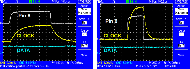
Wafeform of the ringing free clock signal
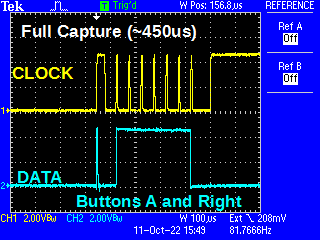
Picture of a full capture
Pictures of the setup
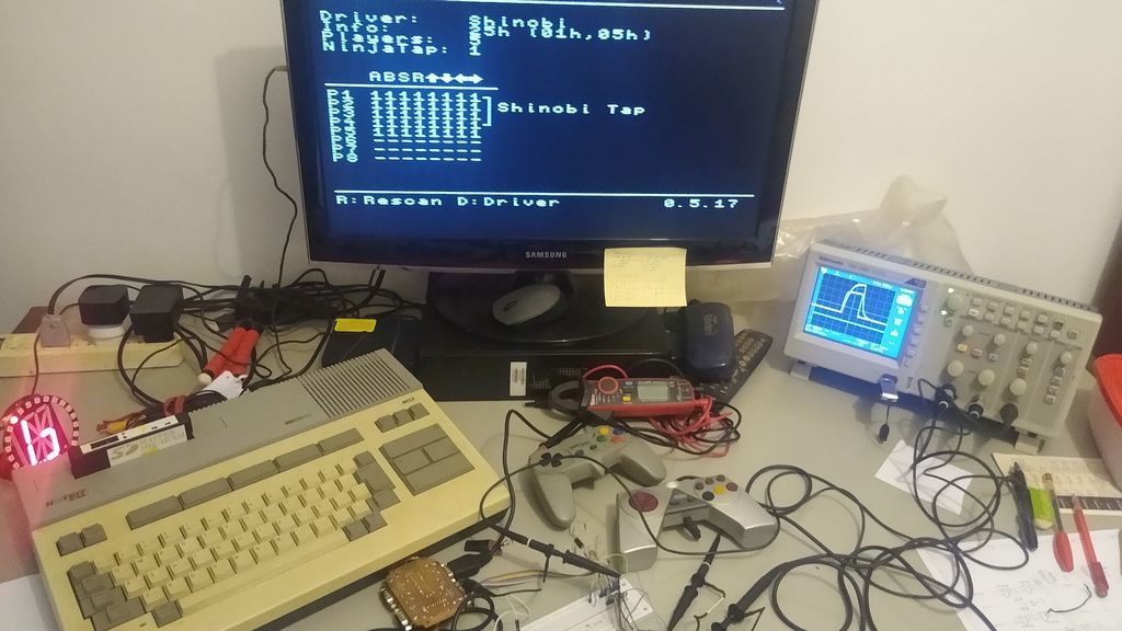
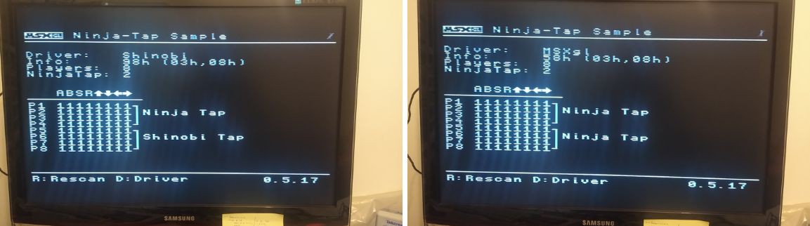
Some screens during test
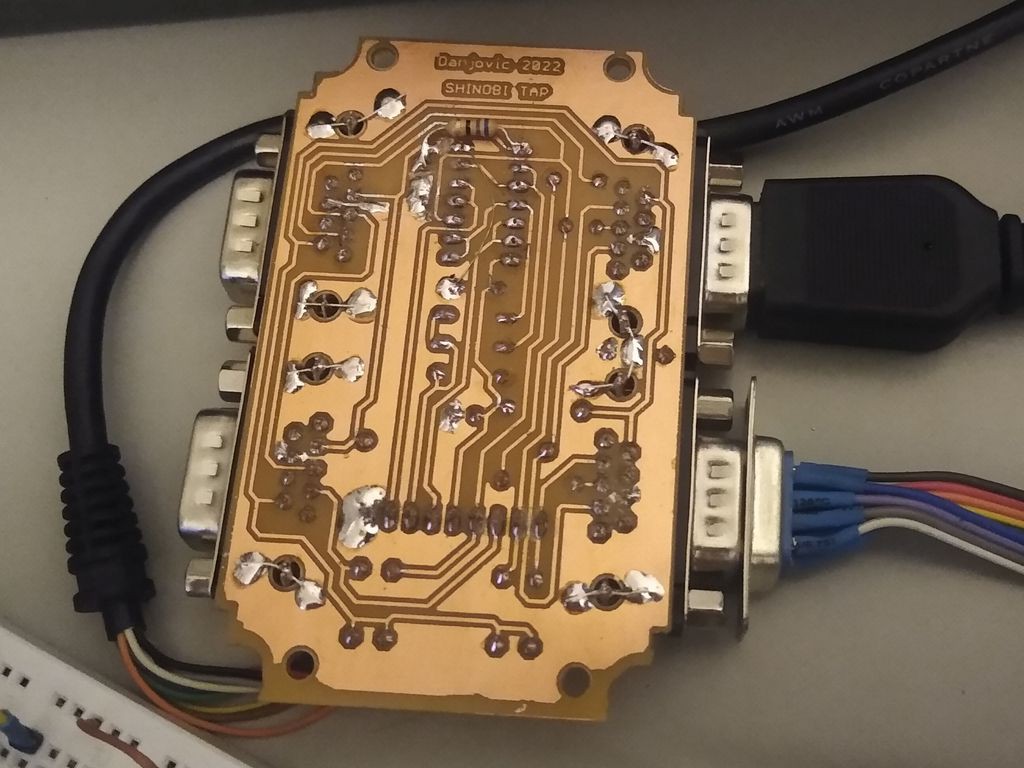
And a closer picture of the prototype. Notice the 10nf ceramic capacitor at the left of the HCT00.
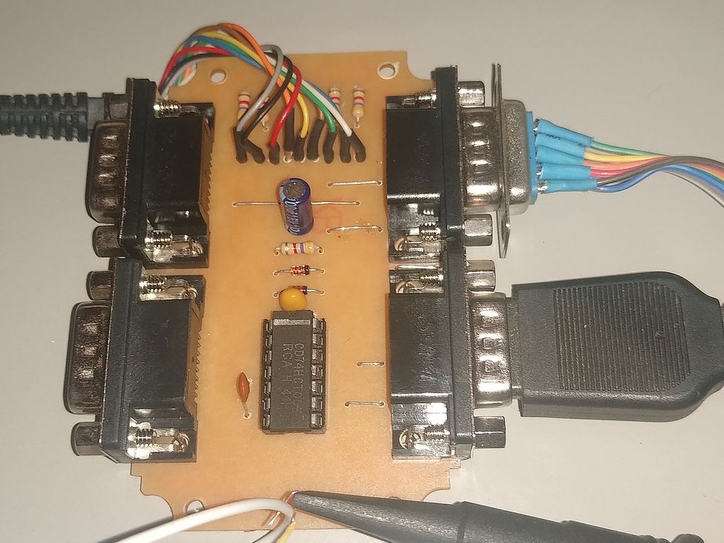
The resistor is under the board.
Discussions
Become a Hackaday.io Member
Create an account to leave a comment. Already have an account? Log In.