Link: IQ data for dummies
Link: Generating Complex Baseband and Analytic Bandpass Signals
Link: I and Q Components in Communications Signals and Single Sideband
IQ (In-phase and Quadrature)
There are a lot of literature that explains the dark-magic around IQ signals, but in essence, together they form a complex number, which can be represented as a real and imaginary value - or magnitude and phase.
I and Q amplitude form a combined amplitude and a phase.
When two waves (complex IQ) are mixed, the phase difference between to two waves determine if resulting wave will undergo constructive or destructive interference.
Given two microphones that records a sound from some angle, the same sound is recorded by both microphones, but with a time delay. The time delay corresponds to the angle from where the sound originated or a difference in phase between the two signals.
Time delay for element j (tde)
where angle is the direction that we want to listen (steering the beam), pde(j) is the phase for element j, and c is the speed of sound
Phase delay for element j (pde) in array:
where ne is the number of elements in the array, d is the element spacing
Sample delay for element j. Note that "center" channel is the ne/2'th element.
Sampling the data from the elements (channels)
When sampling data from the array's elements, we sample real values. The phase is missing from the sampling.
To generate the phase in order for us to generate the IQ data, we need to run the Hilbert transform
where real is the sample data per channel and iq (in timedomain)
Combining all the channels with IQ data, we get a NxM matrix of IQ data, where N (rows) is the number of samples per channel and M (col) is the number of channels.
Beam forming using FFT
Beam forming the data i.e. transforming the data from time domain frequency domain or from channels to beams is simple:
where IQ is in frequency domain and FFT is a 1D transform in the channel direction
Now each col in the matrix represents the frequency data in angle direction.
Angles in the beam formed data:
where i is the i'th beam, c is the speed of sound, ne is the number of elements, d is the element spacing, f is the frequency.
Note that the angle now become dependant of the frequency of the signal. Listening to multifrequency signals like whale song, changes (calculated) angle when whales sing. FFT's are probably not the best way to detect direction when frequency varies
Example:
If we want to calculate the angle for a f=200kHz, where ne=256, d=0.02m for the beam i=100, the angle is -0.51 degrees. Changing the frequency to 220kHz, the angle is -0.47deg. A small change, if we do a chirp.
Using f=2kHz, the angle is -64deg and for f=3kHz, the angle is -37deg. The frequency sweep is impossible to beam form for lower frequencies with larger bandwidth.
Beam forming using CZT transform
Chirp-Z transform or zoom-FFT is a variant of the FFT. It consist of 2x forward FFT and 1x Inverse FFT, so its requires 3x computations. The advantage is that the CZT allows us to specify the angles in the transform, basically letting us zoom into a pre-defined angle-space.
One of the biggest advantages is that the angle calculations are independent of the frequency. Angle space is the same, regardless of the frequency, which is what we want.
Further, we can specify the angles in the angle space we want to use, where as the FFT is pre-set to a specific angle space.
where a1 and a2 are the zoom angles, ne is the number of elements. Notice that angle space is only defined by the zoom angles and number of elements.
Clearly, CZT is the preferred beam former, if FFT's are to be used.
Further, the open angle is worth to revisit.
Open angle specify the outer limits of the a1 and a2, we make sure that we do not conflict with the grating lopes of the beam radiation pattern. This will cause "mirror" effects in the final image.
Example:
open angle is 94 deg when c=330m/s, d=0.01m, f=20000Hz. This means that a1 can be set to -45deg and a2 to +45deg. Too narrow, you will not be able to see much except straight forward.
Range compression
also called match filter. This is simply a complex FIR filter, where filter coefficients are complex (transmit pulse) and the IQ data.
Think of the match filter being a correlation function, where result shows spikes where input echos and transmitted pulse are correlated.
Match filtering can be done in time domain or in frequency domain. Running FFT's in CUDA, its actually faster to do this in frequency domain
Example:
The top image is a pulse mixed with random noise. Pulse is starting at sample 200 and i 240 samples long.
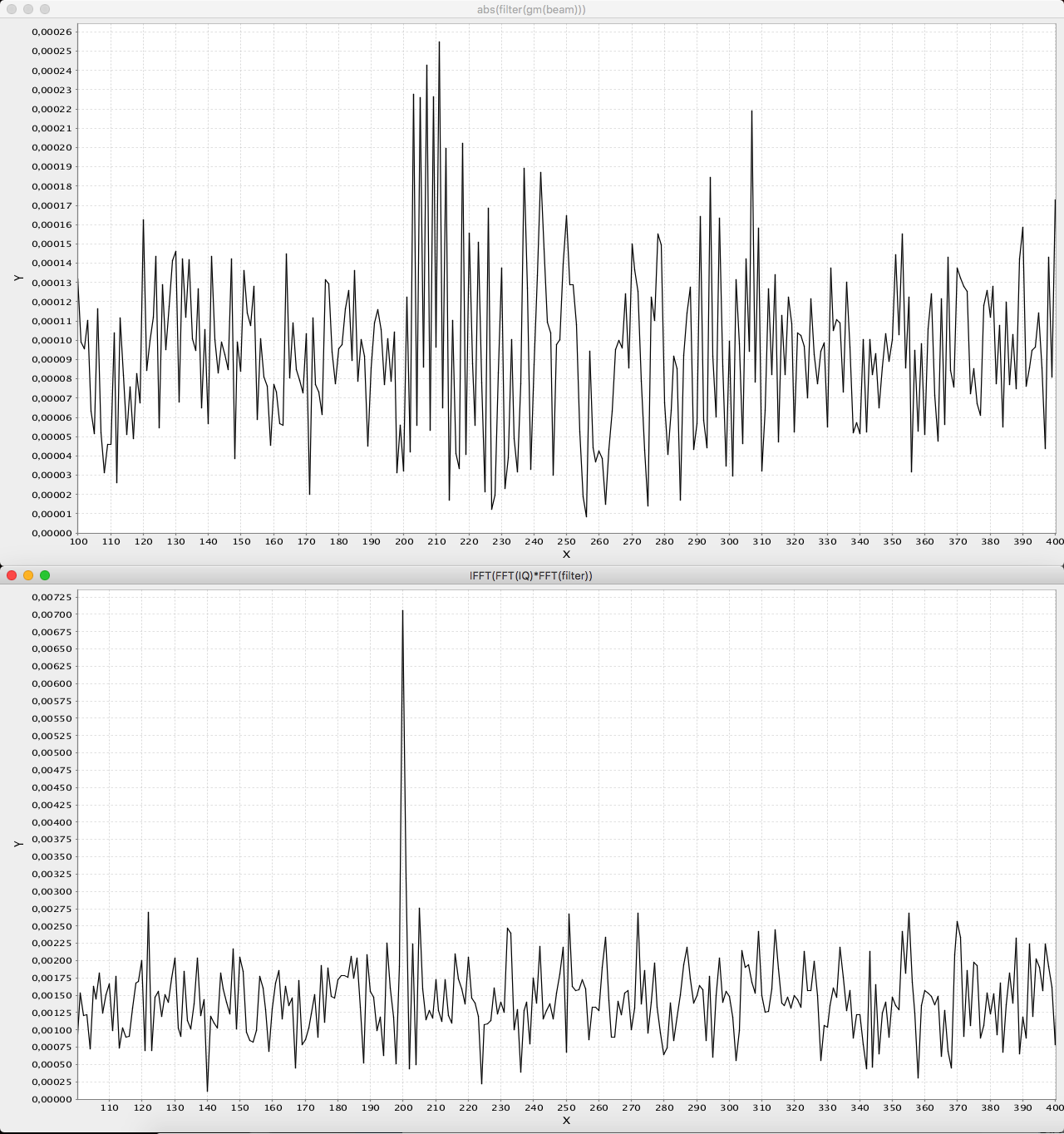
Bottom image is the match filtered pulse. Note that the pulse is shortened (compressed) and the surrounding noise is heavily reduced.
Signal processing
Discussions
Become a Hackaday.io Member
Create an account to leave a comment. Already have an account? Log In.