 finallyfunctional
In this article I'm going to go over a 2in diameter omnidirectional sphere I designed.
Prior Designs and Builds
The design is based of what is shown in this video.
This video shows the same design, but scaled up and 3D printed.
Requirements of the Omniwheel
For my next VR shoe I want to use omnidirectional wheels, but they need to fulfill some criteria.
- They need to be small enough to fit into a VR shoe. I'd like the wheels to be a maximum of 2in tall.
- They need to be able to hold my weight (approximately 170 pounds).
- I want them to work on the thin (1/8in thick) rubber mat I've been using so that noise is reduced, or they need to be quite on their own.
The omniwheels I've used in the past, Rotacaster, don't meet these criteria and I believe most omniwheels in general don't. They are a little noisy on their own and cannot be used on my mat, because the whee's frame would rub against the mat. Additionally, I'd have to combine several of them to hold my weight.
The spherical wheels in the videos above looked to me like they could be quiet, work on a rubber mat, and be designed to handle my body weight. The last part was to make them small enough, but I managed to reduce their size to 2in in diameter.
Demo of my Design
Here is a short video showing my design.
Design Details
For how the wheel works, here is an image of the design that shows some of the internal details.
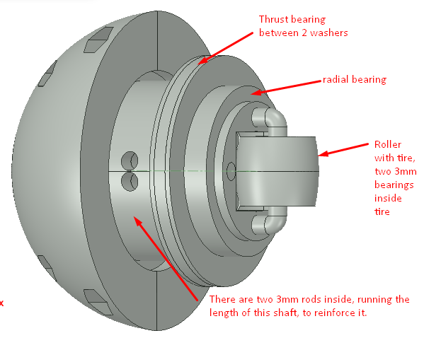
The larger components of the wheel are 2 hemispheres and the shaft. The shaft at its thinnest point is 0.875in in diameter. The shaft and hemispheres are 3D printed out of PETG.
Inside each hemisphere is a thrust bearing, radial bearing, and a roller. The roller has a TPU tire I 3D printed that goes around two 3mm bearings.
When the sphere is "upright" as shown in the image above, the radial bearings will be absorbing the load placed on the it. As the sphere rotates 90 degrees, the thrust bearing will take more and more of the load. When at 90 degrees, the roller will take all of the load.
You can see each hemisphere is cut in half. This makes assembly much easier. The halves of the hemisphere are held together by four 0-80 screws and nuts.
Here is a cross section of the design.
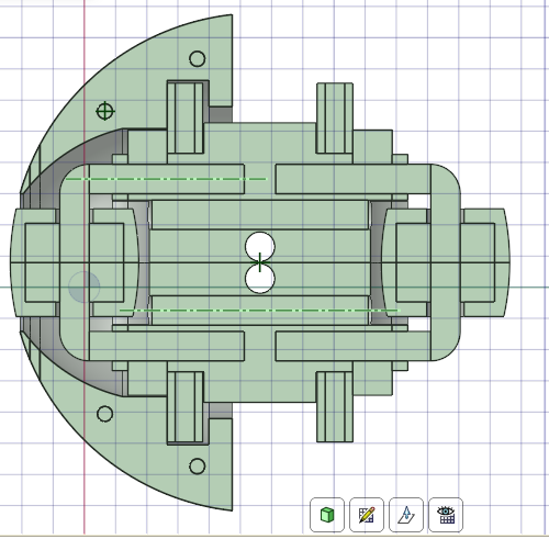
There are two 3mm rods running the length of the shaft to reinforce it. If aspects of the design are still not clear, the next section shows how I assembled the wheel and may clarify how the wheel works.
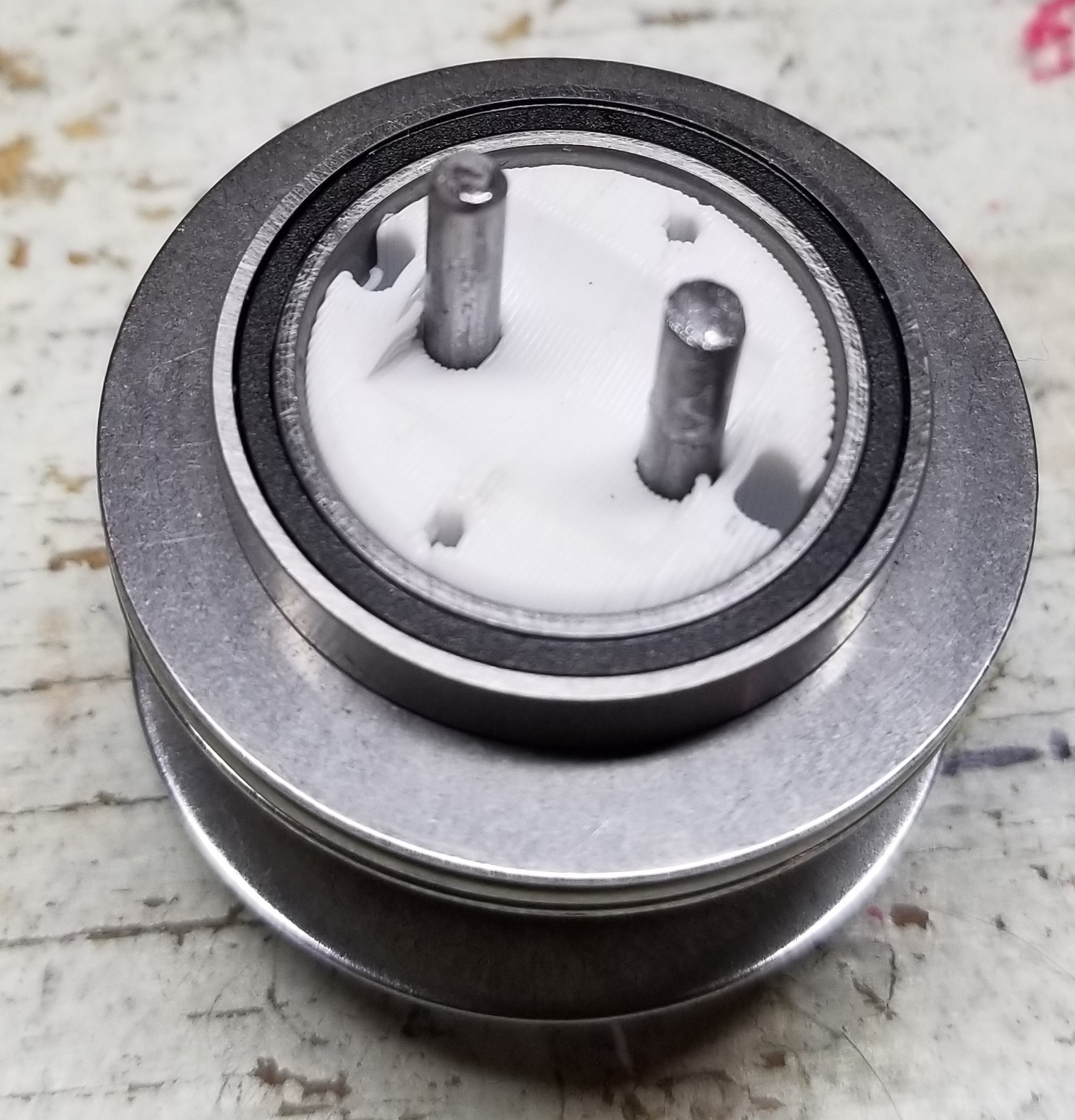
Building the Wheel
You can see in the image below that the shaft is printed in two separate pieces just to make 3D printing it easier and to ensure that the layer lines are perpendicular to the force applied to the shaft. First the thrust bearings and their washers are pushed onto the shaft. The thrust bearings and radial bearings keep the shaft halves together.
Next the radial bearing is pushed onto the shaft.
The two 3mm rods that are used to reinforce the shaft are hammered into it.
The roller is also hammered into the shaft.
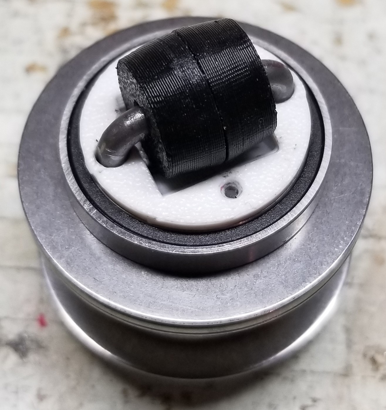
If you're curious as to how I made the roller, I bent one side of the roller's axle in my vice by hand and I 3D printed some parts that allowed me to hold the axle and two 3mm bearings in the vice and bend the other side. I'll go more into detail on this when I eventually make a guide for the VR shoe I plan to build, or I can clarify further if anyone wants to know more details.
You may have noticed in the last image that there is a white cap that was also placed along with the roller. This cap is screwed to the shaft with two 0-80 screws (and some nuts inside the shaft) and its purpose is to keep the radial bearing from popping off. However, the bearing fits so tightly onto the shaft that I don't think it's necessary.
Next one of the hemisphere halves is slid on as shown below.
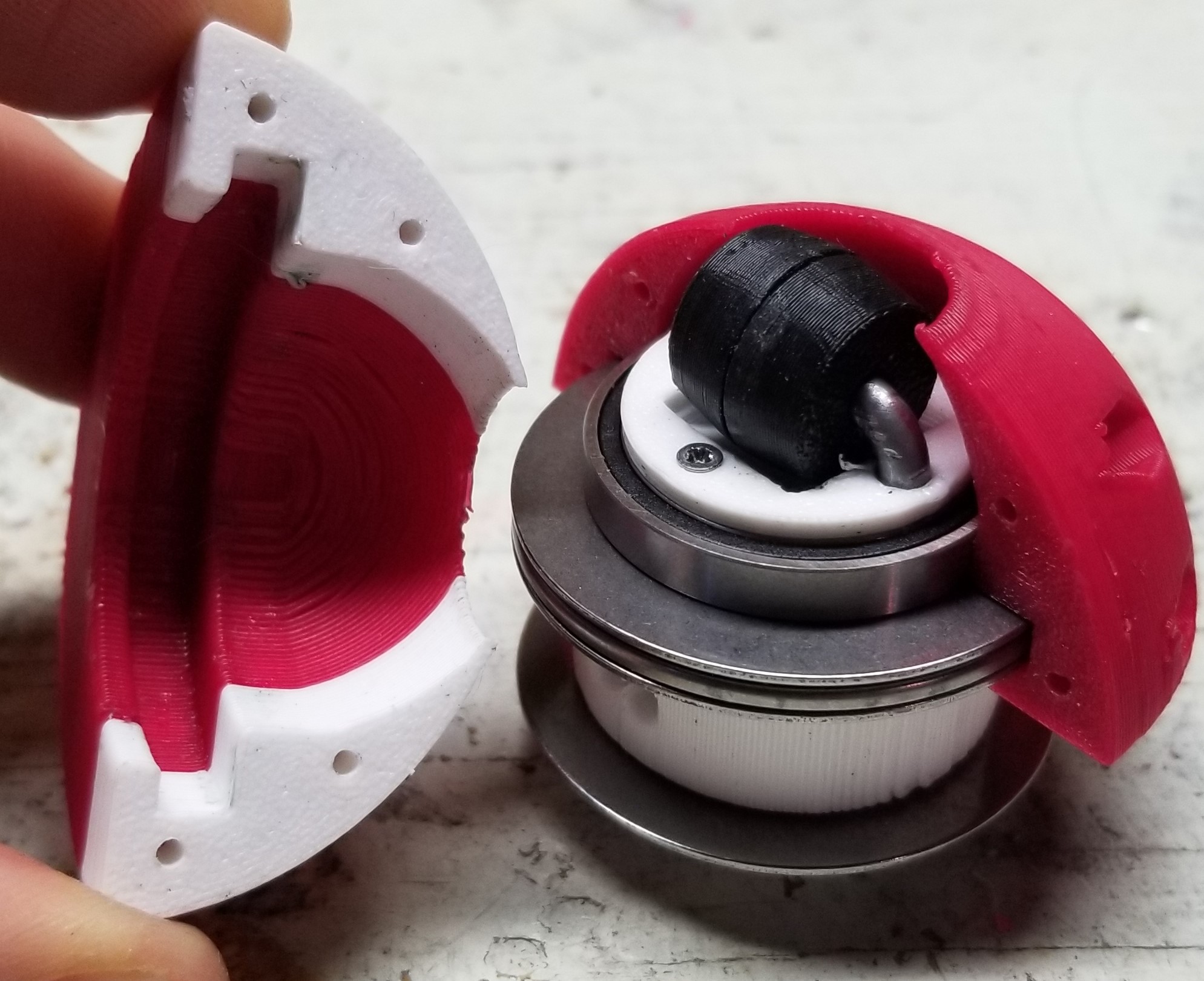
The other half is also slid on and then they are screwed together.
Roller Exposure
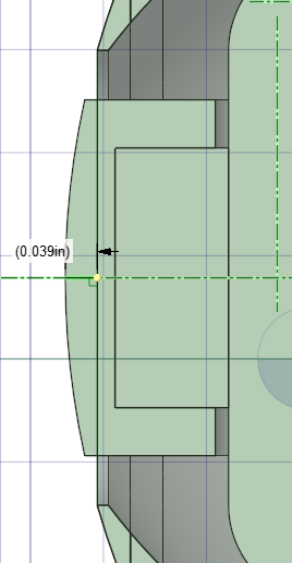
I did some experimenting with how much material to have directly around the roller. You can imagine that if you're using this on a slightly squishy surface and the sphere rotates directly on top of the roller, the roller will sink a little into the squishy surface and then the hemispheres will rub against that surface.
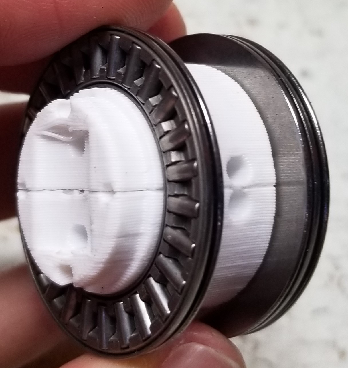
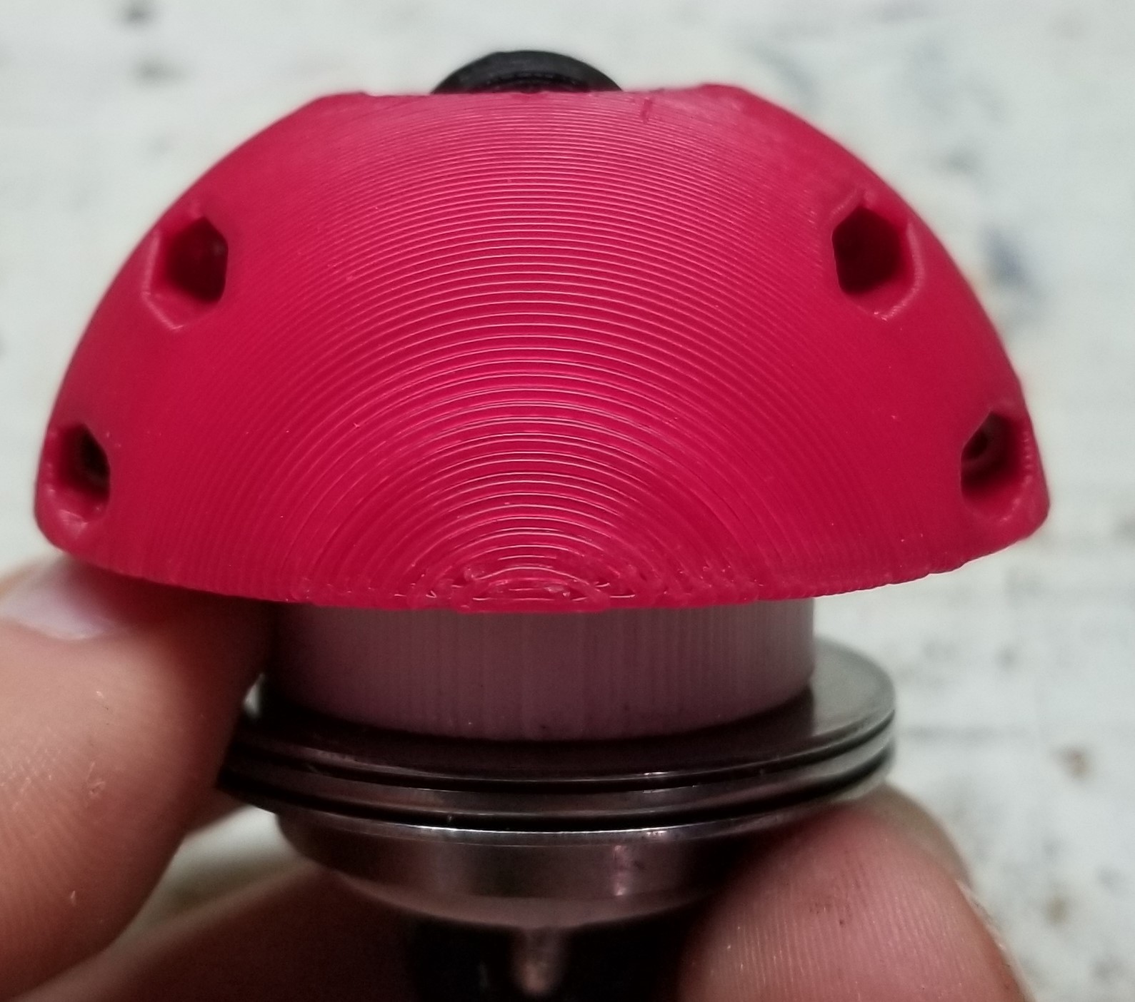
I did three experiments. The first had 0.04in of space between the edge of the roller that would make contact with the surface and the edge of the hemispheres, as shown below.
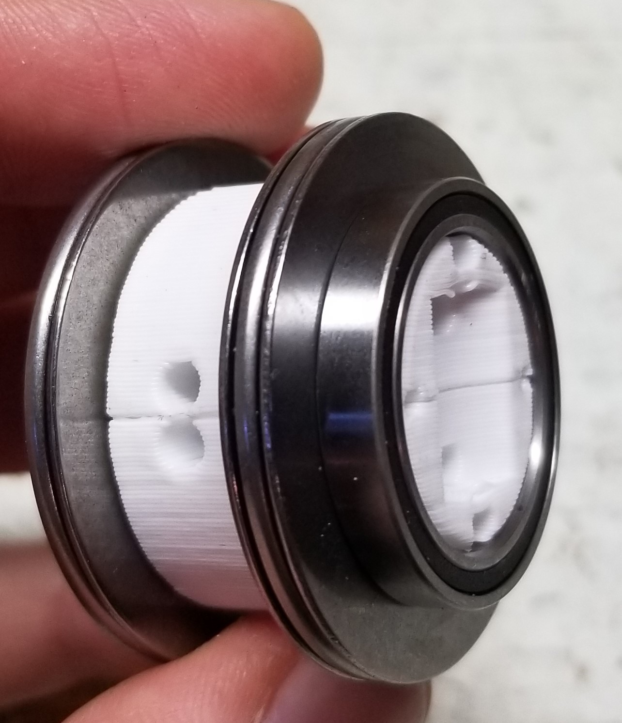
The other spaces I tried were 0.08in and 0.12in. You can see what these different roller exposures look like below.


I wanted to see if there was a terrible bump as the sphere rolls over the roller with these different exposures. With the 0.04in version, I was not able to notice a bump at all, but if I pressed hard on the sphere to make it sink a little into the mat, the hemisphere did rub. With 0.08in, there is a very slight bump and when pressing the sphere I did feel it rub against the mat a few times, but that could possibly be because I was not applying pressure to the sphere evenly. Lastly, with 0.12in there was a slight bump but the rolling motion still felt smooth and the sphere did not rub against the mat.
If using these in a VR shoe I don't think I'd notice the bump made by the 0.12in version very much unless I was really paying attention to it, so I'm going to try out that version in the VR shoe first.
Conclusion
I'm really happy with this design and I'm going to use them in a new omnidirectional VR shoe. The assembled sphere weighed 100 grams and I plan on using four or five of them in a shoe, so the weight shouldn't be much of a problem.
Discussions
Become a Hackaday.io Member
Create an account to leave a comment. Already have an account? Log In.