 Roman
Roman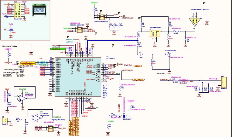
Step 1 is to add LCD and some analog interface to my CC3200MOD board. Schematics link.
CC3200 SimpleLink Wi-Fi and Internet-of-Things solution, a Single-Chip Wireless MCU.
Another CC3200MOD board has arrived as well.
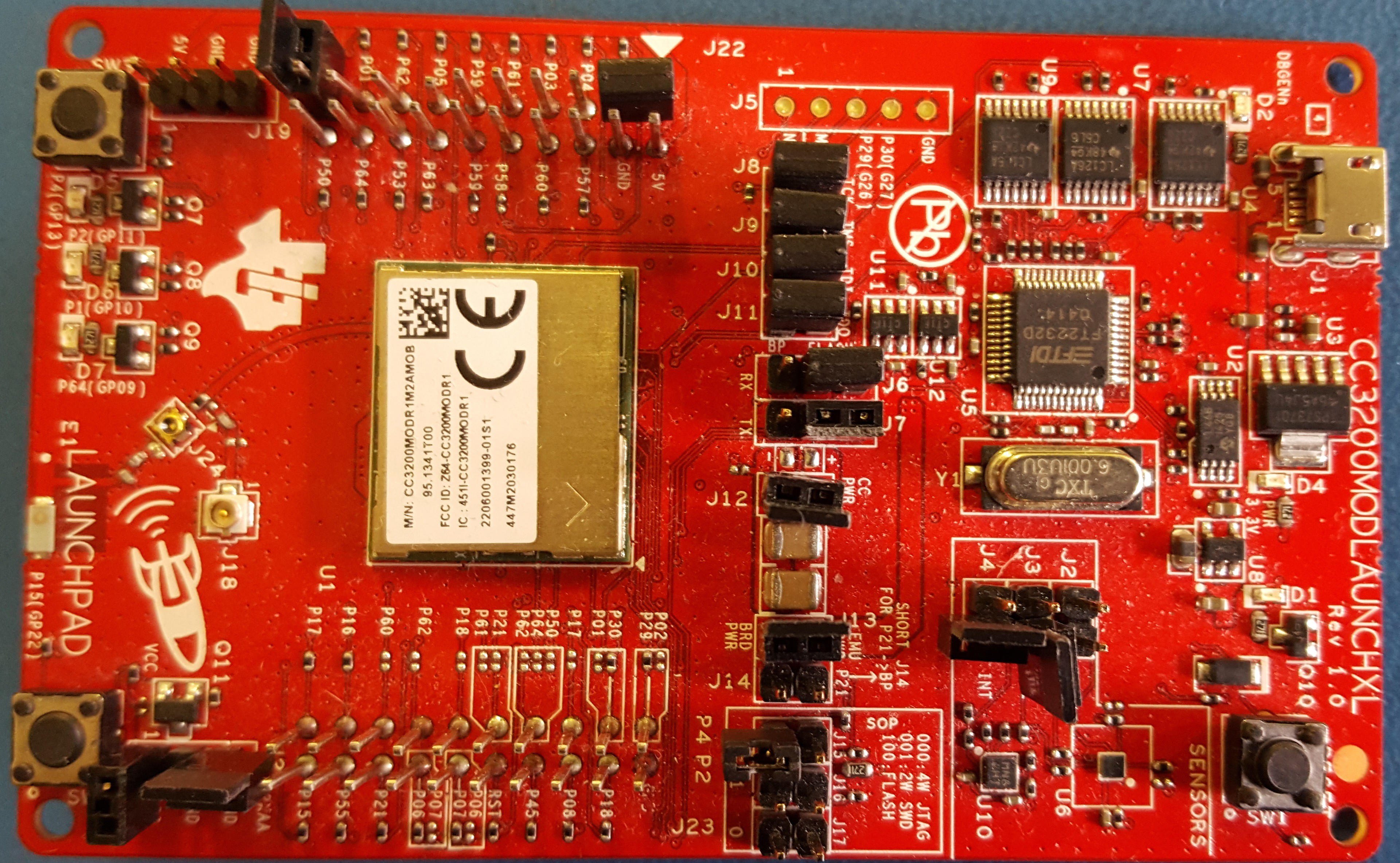
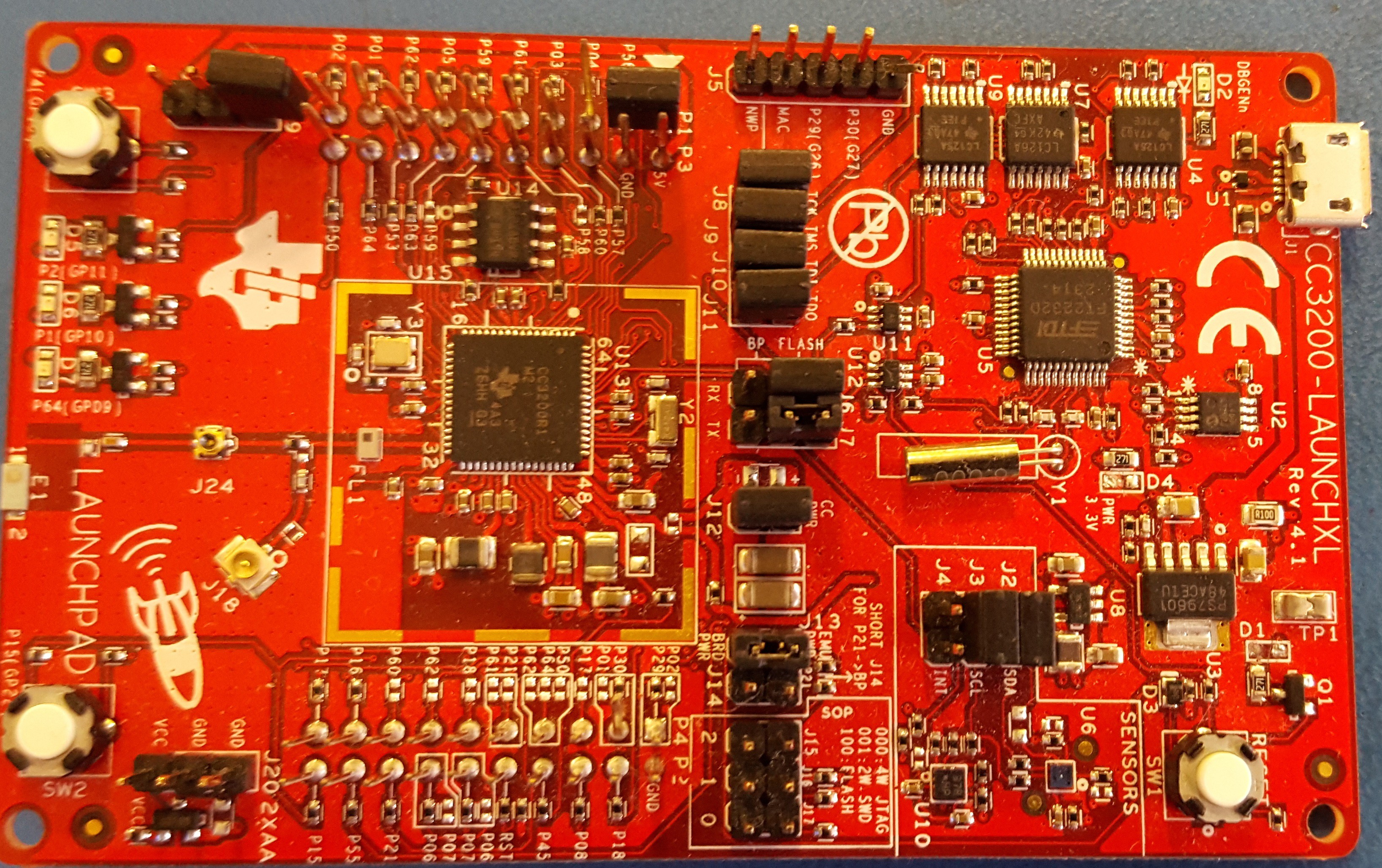
SimpleLink Wi-Fi CC3200 module LaunchPad
Going wireless is fun. My new toys have arrived.
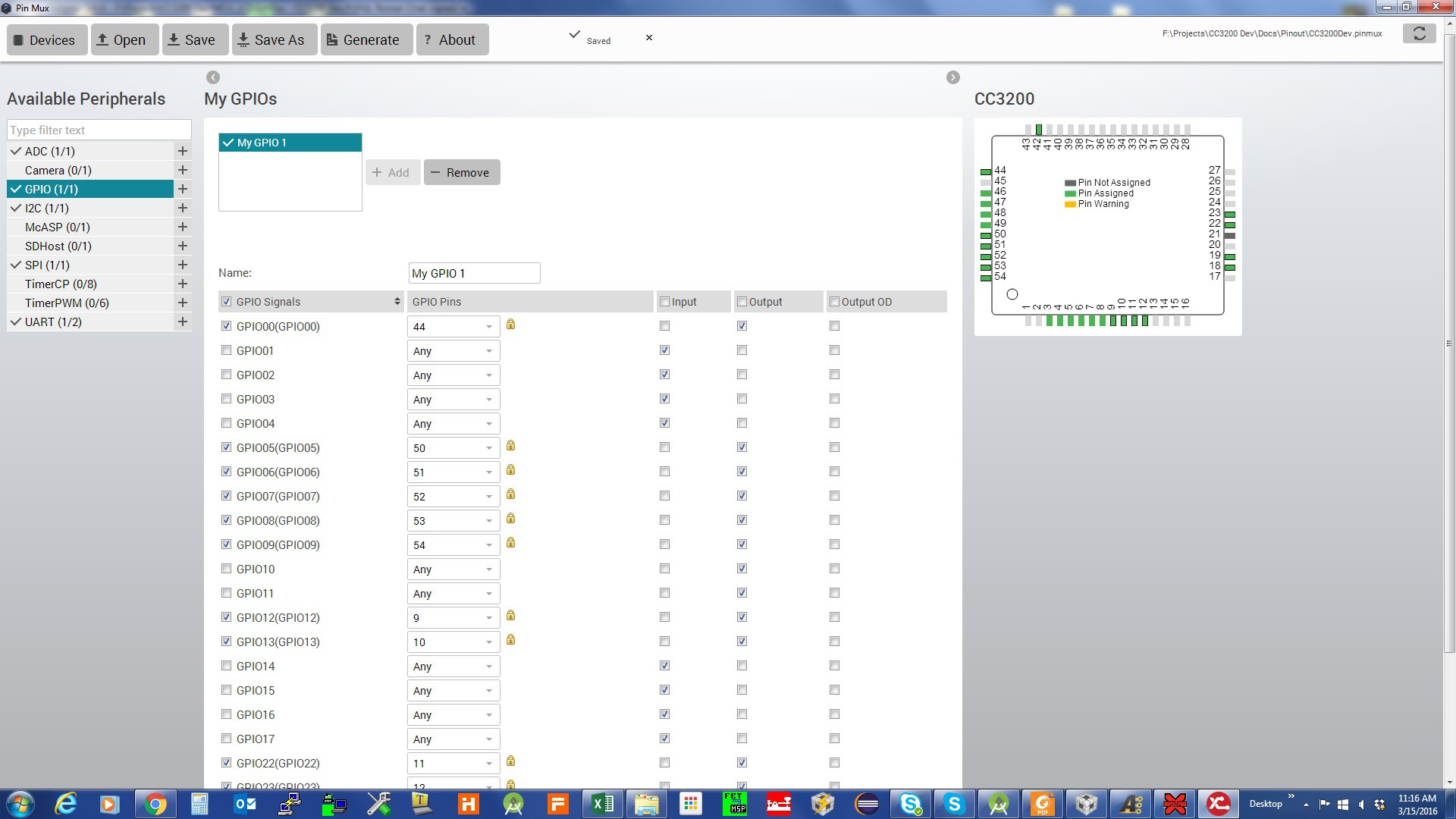
The next step is to set my pins in the code. Ti has a very handy tool for pin assignments Ti Pin Mux ToolPin Mux Tool.
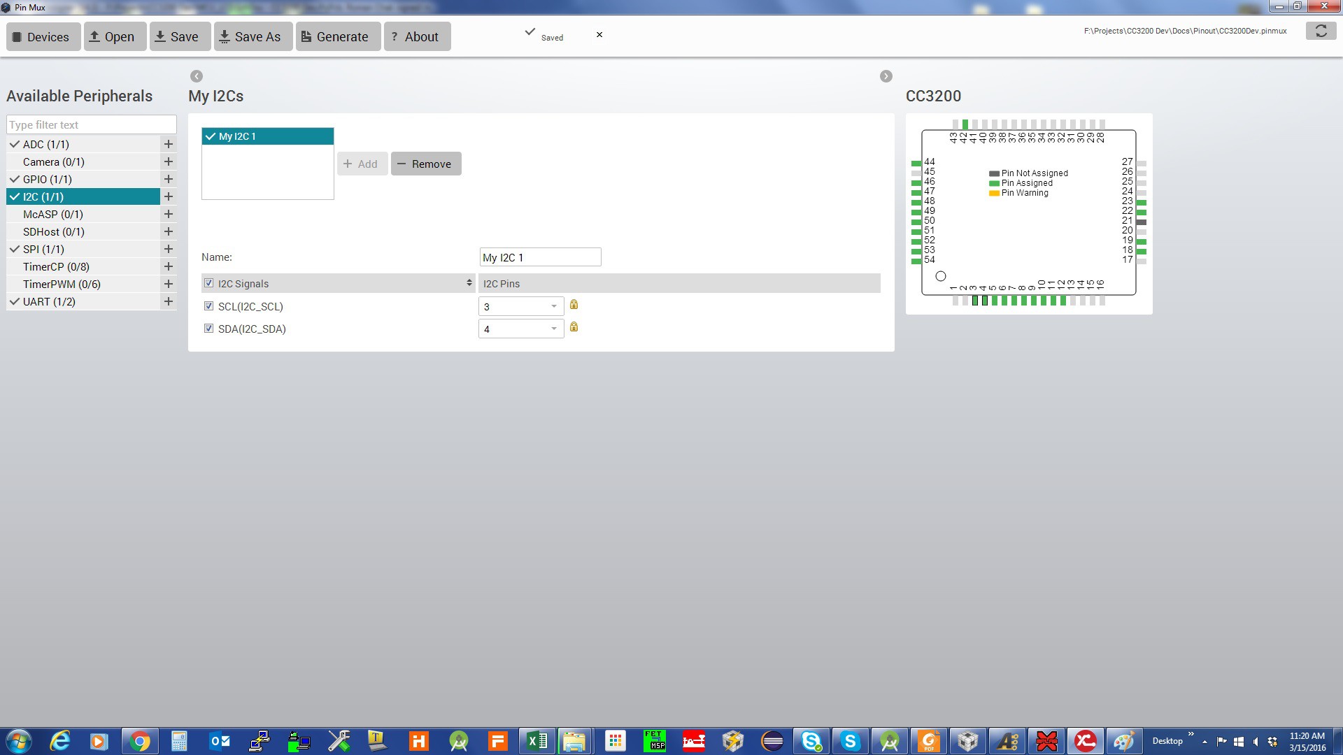
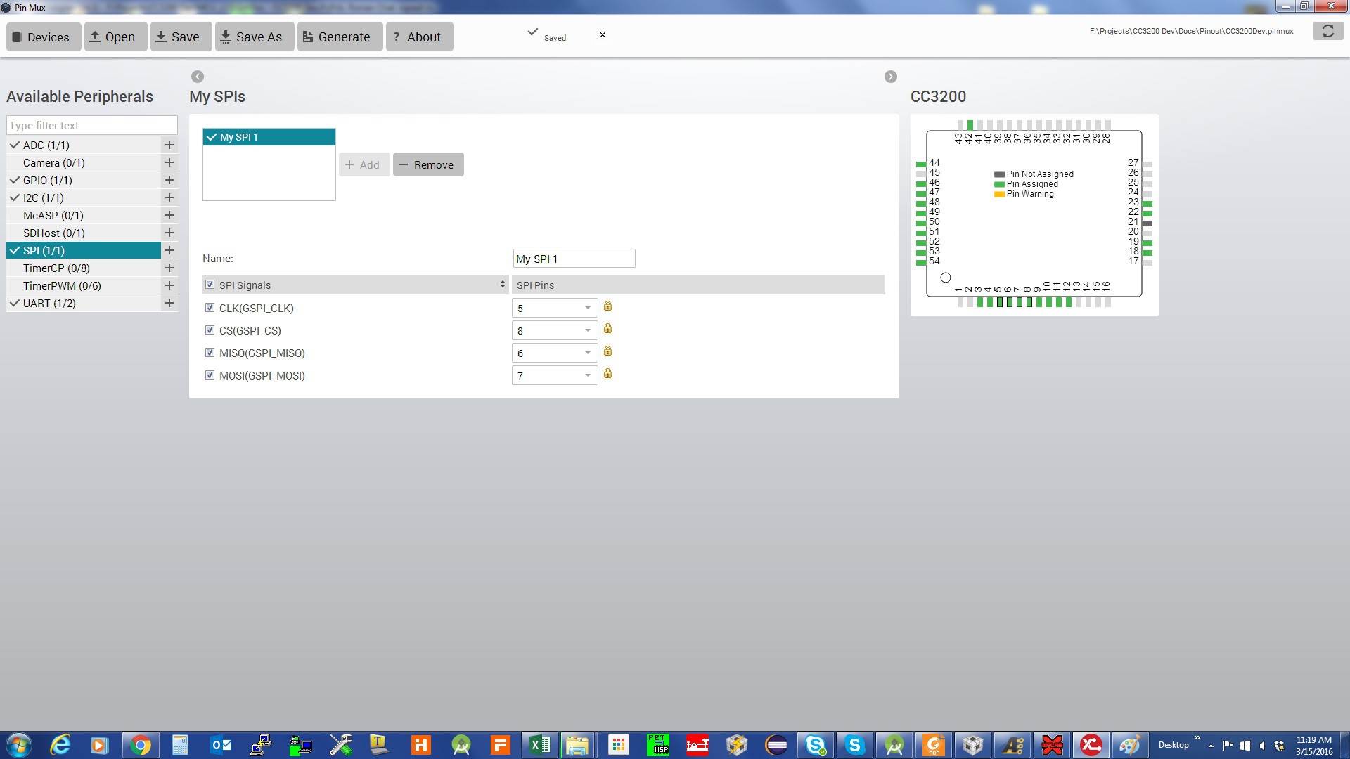
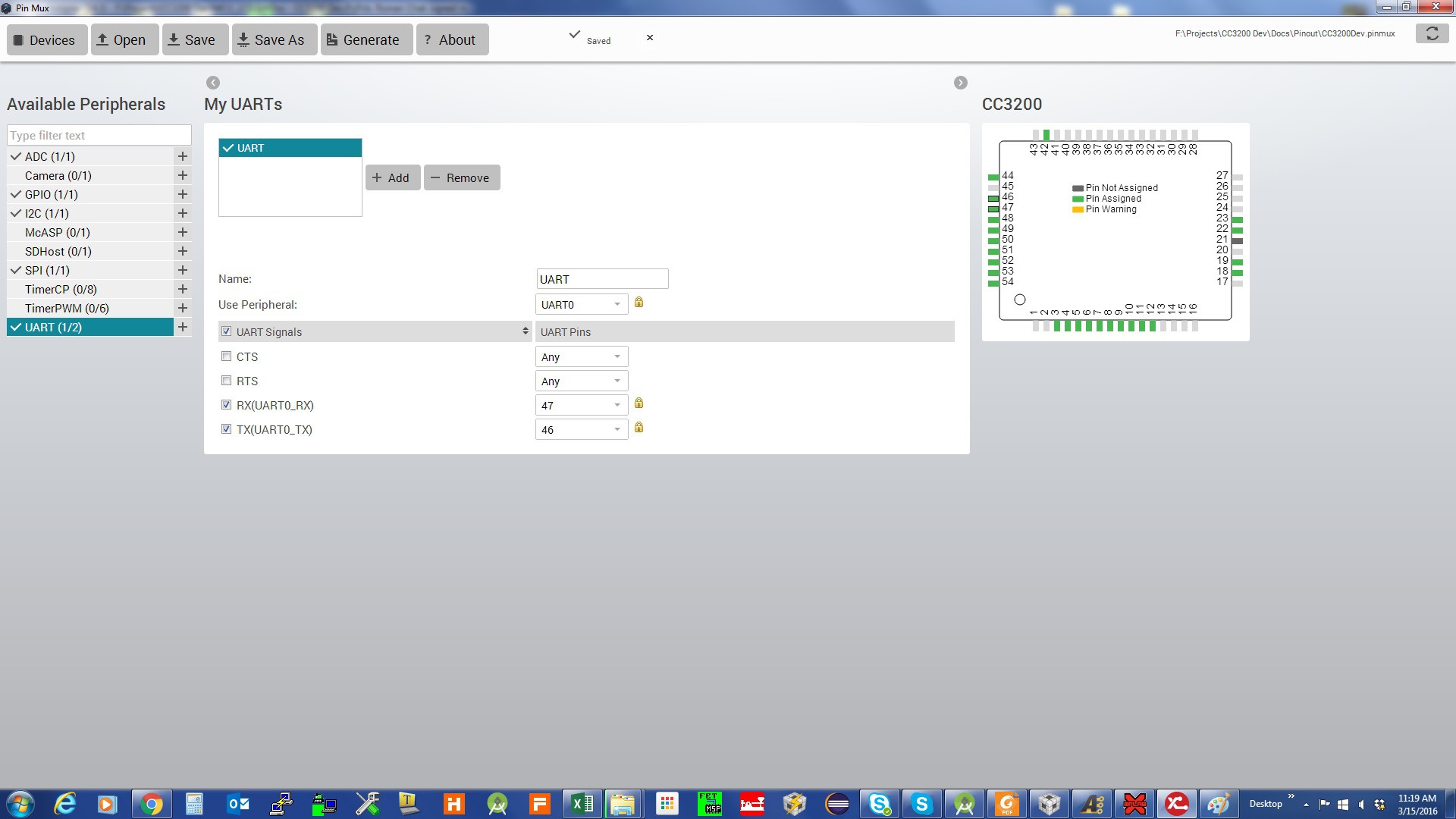
The following are screen shots of the PinMax tool for the project:
Pin assignments for ADC: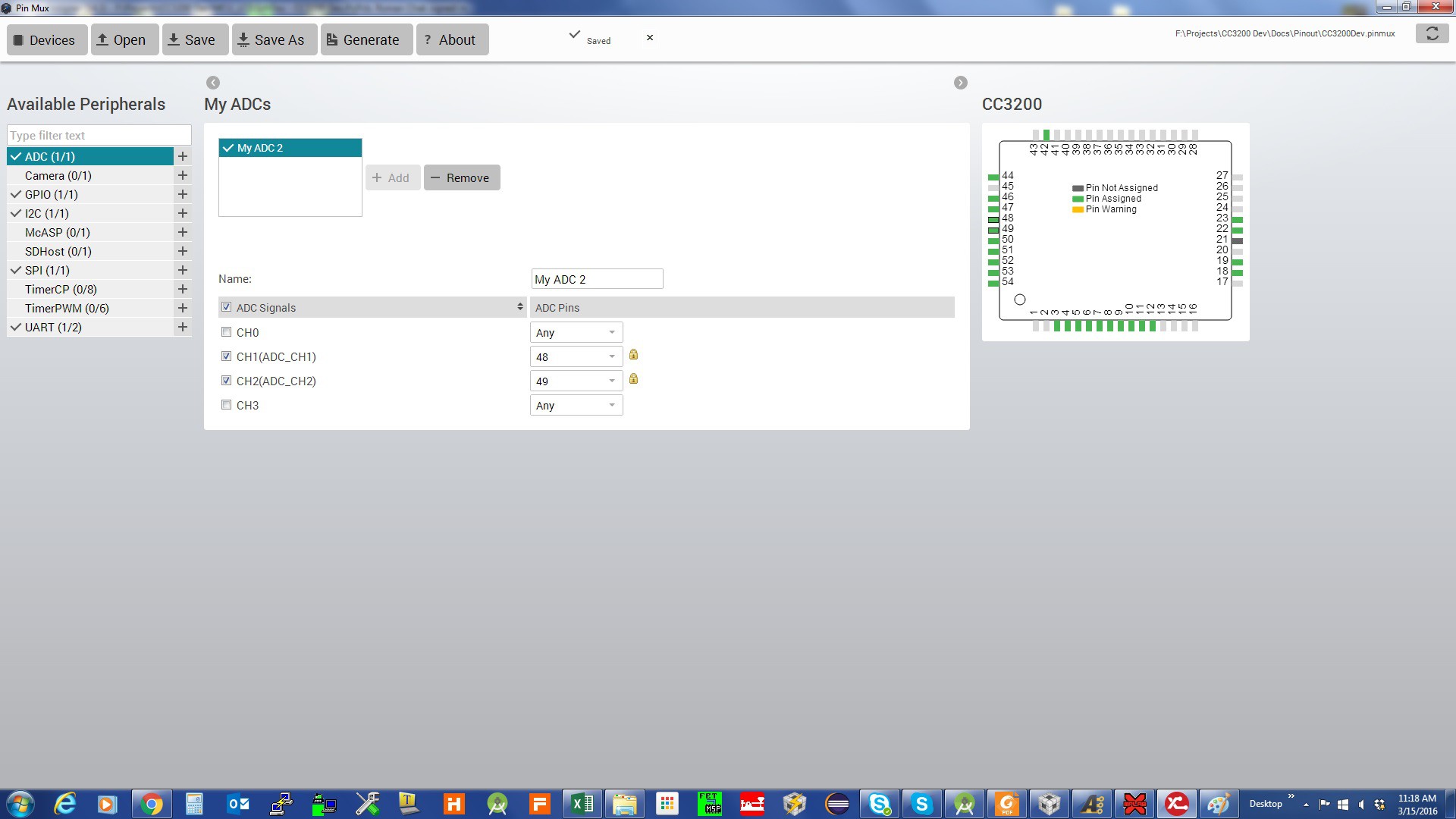
Pin assignments for GPIO:
Pin assignments for I2C:
Pin assignments for SPI:
Pin assignments for UART:
The result is:
//*****************************************************************************
// pin_mux_config.c
//
// configure the device pins for different signals
//
// Copyright (C) 2014 Texas Instruments Incorporated - http://www.ti.com/
//
//
//  Redistribution and use in source and binary forms, with or without
//  modification, are permitted provided that the following conditions
//  are met:
//
//    Redistributions of source code must retain the above copyright
//    notice, this list of conditions and the following disclaimer.
//
//    Redistributions in binary form must reproduce the above copyright
//    notice, this list of conditions and the following disclaimer in the
//    documentation and/or other materials provided with the
//    distribution.
//
//    Neither the name of Texas Instruments Incorporated nor the names of
//    its contributors may be used to endorse or promote products derived
//    from this software without specific prior written permission.
//
//  THIS SOFTWARE IS PROVIDED BY THE COPYRIGHT HOLDERS AND CONTRIBUTORS
//  "AS IS" AND ANY EXPRESS OR IMPLIED WARRANTIES, INCLUDING, BUT NOT
//  LIMITED TO, THE IMPLIED WARRANTIES OF MERCHANTABILITY AND FITNESS FOR
//  A PARTICULAR PURPOSE ARE DISCLAIMED. IN NO EVENT SHALL THE COPYRIGHT
//  OWNER OR CONTRIBUTORS BE LIABLE FOR ANY DIRECT, INDIRECT, INCIDENTAL,
//  SPECIAL, EXEMPLARY, OR CONSEQUENTIAL DAMAGES (INCLUDING, BUT NOT
//  LIMITED TO, PROCUREMENT OF SUBSTITUTE GOODS OR SERVICES; LOSS OF USE,
//  DATA, OR PROFITS; OR BUSINESS INTERRUPTION) HOWEVER CAUSED AND ON ANY
//  THEORY OF LIABILITY, WHETHER IN CONTRACT, STRICT LIABILITY, OR TORT
//  (INCLUDING NEGLIGENCE OR OTHERWISE) ARISING IN ANY WAY OUT OF THE USE
//  OF THIS SOFTWARE, EVEN IF ADVISED OF THE POSSIBILITY OF SUCH DAMAGE.
//
//*****************************************************************************

// This file was automatically generated on 3/15/2016 at 12:31:19 AM
// by TI PinMux version 3.0.625
//
//*****************************************************************************

#include "pin_mux_config.h"
#include "hw_types.h"
#include "hw_memmap.h"
#include "hw_gpio.h"
#include "pin.h"
#include "gpio.h"
#include "prcm.h"

//*****************************************************************************
void PinMuxConfig(void)
{
    //
    // Enable Peripheral Clocks
    //
    PRCMPeripheralClkEnable(PRCM_ADC, PRCM_RUN_MODE_CLK);
    PRCMPeripheralClkEnable(PRCM_UARTA0, PRCM_RUN_MODE_CLK);
    PRCMPeripheralClkEnable(PRCM_GSPI, PRCM_RUN_MODE_CLK);
    PRCMPeripheralClkEnable(PRCM_I2CA0, PRCM_RUN_MODE_CLK);
    PRCMPeripheralClkEnable(PRCM_GPIOA0, PRCM_RUN_MODE_CLK);
    PRCMPeripheralClkEnable(PRCM_GPIOA1, PRCM_RUN_MODE_CLK);
    PRCMPeripheralClkEnable(PRCM_GPIOA2, PRCM_RUN_MODE_CLK);
    PRCMPeripheralClkEnable(PRCM_GPIOA3, PRCM_RUN_MODE_CLK);

    //
    // Configure PIN_58 for ADC0 ADC_CH1
    //
    PinTypeADC(PIN_58, PIN_MODE_255);

    //
    // Configure PIN_59 for ADC0 ADC_CH2
    //
    PinTypeADC(PIN_59, PIN_MODE_255);

    //
    // Configure PIN_55 for UART0 UART0_TX
    //
    PinTypeUART(PIN_55, PIN_MODE_3);

    //
    // Configure PIN_57 for UART0 UART0_RX
    //
    PinTypeUART(PIN_57, PIN_MODE_3);

    //
    // Configure PIN_08 for SPI0 GSPI_CS
    //
    PinTypeSPI(PIN_08, PIN_MODE_7);

    //
    // Configure PIN_05 for SPI0 GSPI_CLK
    //
    PinTypeSPI(PIN_05, PIN_MODE_7);

    //
    // Configure PIN_06 for SPI0 GSPI_MISO
    //
    PinTypeSPI(PIN_06, PIN_MODE_7);

    //
    // Configure PIN_07 for SPI0 GSPI_MOSI
    //
    PinTypeSPI(PIN_07, PIN_MODE_7);

    //
    // Configure PIN_01 for I2C0 I2C_SCL
    //
    PinTypeI2C(PIN_01, PIN_MODE_1);

    //
    // Configure PIN_02 for I2C0 I2C_SDA
    //
    PinTypeI2C(PIN_02, PIN_MODE_1);

    //
    // Configure PIN_50 for GPIO Output
    //
    PinTypeGPIO(PIN_50, PIN_MODE_0, false);
    GPIODirModeSet(GPIOA0_BASE, 0x1, GPIO_DIR_MODE_OUT);

    //
    // Configure PIN_60 for GPIO Output
    //
    PinTypeGPIO(PIN_60, PIN_MODE_0, false);
    GPIODirModeSet(GPIOA0_BASE, 0x20, GPIO_DIR_MODE_OUT);

    //
    // Configure PIN_61 for GPIO Output
    //
    PinTypeGPIO(PIN_61, PIN_MODE_0, false);
    GPIODirModeSet(GPIOA0_BASE, 0x40, GPIO_DIR_MODE_OUT);

    //
    // Configure PIN_62 for GPIO Output
    //
    PinTypeGPIO(PIN_62, PIN_MODE_0, false);
    GPIODirModeSet(GPIOA0_BASE, 0x80, GPIO_DIR_MODE_OUT);

    //
    // Configure PIN_63 for GPIO Output
    //
    PinTypeGPIO(PIN_63, PIN_MODE_0, false);
    GPIODirModeSet(GPIOA1_BASE, 0x1, GPIO_DIR_MODE_OUT);

    //
    // Configure PIN_64 for GPIO Output
    //
    PinTypeGPIO(PIN_64, PIN_MODE_0, false);
    GPIODirModeSet(GPIOA1_BASE, 0x2, GPIO_DIR_MODE_OUT);

    //
    // Configure PIN_03 for GPIO Output
    //
    PinTypeGPIO(PIN_03, PIN_MODE_0, false);
    GPIODirModeSet(GPIOA1_BASE, 0x10, GPIO_DIR_MODE_OUT);

    //
    // Configure PIN_04 for GPIO Output
    //
    PinTypeGPIO(PIN_04, PIN_MODE_0, false);
    GPIODirModeSet(GPIOA1_BASE, 0x20, GPIO_DIR_MODE_OUT);

    //
    // Configure PIN_15 for GPIO Output
    //
    PinTypeGPIO(PIN_15, PIN_MODE_0, false);
    GPIODirModeSet(GPIOA2_BASE, 0x40, GPIO_DIR_MODE_OUT);

    //
    // Configure PIN_16 for GPIO Output
    //
    PinTypeGPIO(PIN_16, PIN_MODE_0, false);
    GPIODirModeSet(GPIOA2_BASE, 0x80, GPIO_DIR_MODE_OUT);

    //
    // Configure PIN_17 for GPIO Output
    //
    PinTypeGPIO(PIN_17, PIN_MODE_0, false);
    GPIODirModeSet(GPIOA3_BASE, 0x1, GPIO_DIR_MODE_OUT);

    //
    // Configure PIN_18 for GPIO Output
    //
    PinTypeGPIO(PIN_18, PIN_MODE_0, false);
    GPIODirModeSet(GPIOA3_BASE, 0x10, GPIO_DIR_MODE_OUT);

    //
    // Configure PIN_20 for GPIO Output
    //
    PinTypeGPIO(PIN_20, PIN_MODE_0, false);
    GPIODirModeSet(GPIOA3_BASE, 0x20, GPIO_DIR_MODE_OUT);

    //
    // Configure PIN_21 for GPIO Output
    //
    PinTypeGPIO(PIN_21, PIN_MODE_0, false);
    GPIODirModeSet(GPIOA3_BASE, 0x2, GPIO_DIR_MODE_OUT);

    //
    // Configure PIN_53 for GPIO Output
    //
    PinTypeGPIO(PIN_53, PIN_MODE_0, false);
    GPIODirModeSet(GPIOA3_BASE, 0x40, GPIO_DIR_MODE_OUT);
}
Discussions
Become a Hackaday.io Member
Create an account to leave a comment. Already have an account? Log In.