 djBo
djBoA few years ago, I created a small project to get a NCR 65C02 running on a breadboard. A Teensy 2.0 was responsible for generating the cpu clock signal, while I was using a Teensy 3.1 as a ROM programmer. Inspired by the RC2014 project, I wanted to build something similar but based on the 6502.
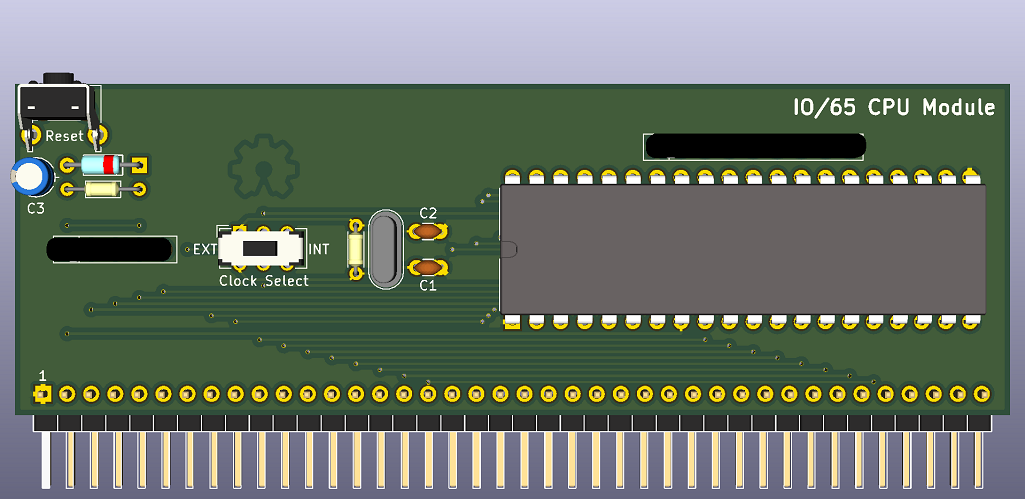
So here's the basic design of the very first module.
The circuit and board layout were made using KiCAD. It measures 105*35 mm, exposes most of the control signals, and provides standalone free-running when powered.
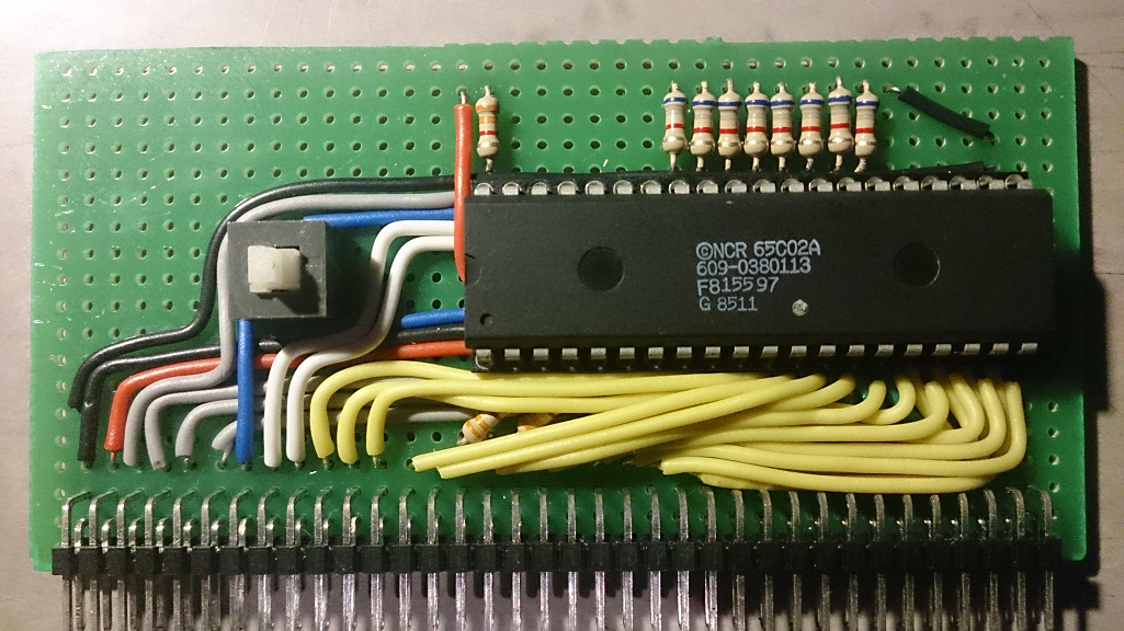
So this is what I ended up with. I excluded the reset button, and am using a 2*36 pin header instead. I did include the clock select switch, as I still don't have the required 1MHz crystal.
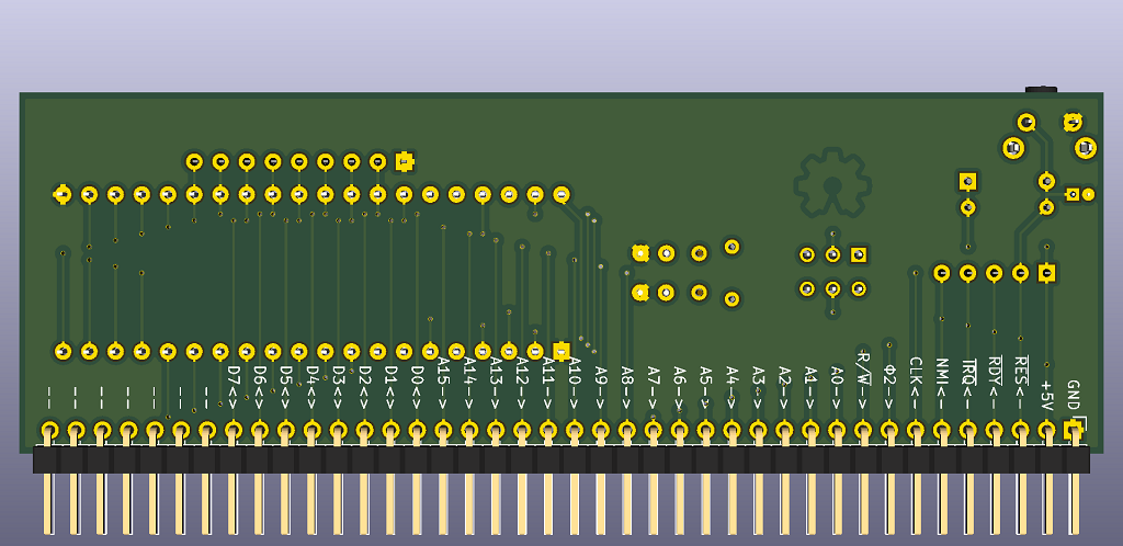
I probably shouldn't be running all them lines over and across each other. In hindsight, I could have exposed some additional pins. I did however use the exact same pinout as my initial design.
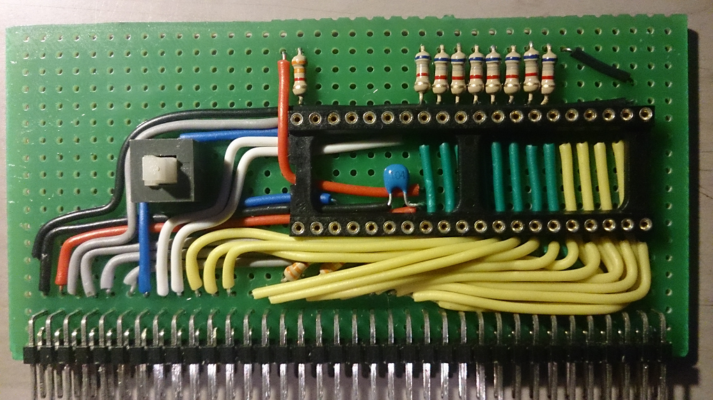
The change to the 36-pin header does have a reason. I wanted to build the initial backplane using a stripboard like this. And since I already have a few of these 2*36 angled headers and a set of female header rows, I'm good to go!
My initial tests proved the board was working as intended, with the cpu executing BRK (0x00) instructions forever.
See you in part #2 :)
Discussions
Become a Hackaday.io Member
Create an account to leave a comment. Already have an account? Log In.