 TwinkleTwinkie
I fucked up. I fucked up 250 Shitty Add-on boards. Those 250 boards and the 300 I ordered to replace them, replacement parts, and solder reworking station cost me more than half my overall Badge Life expenses this year. To give you an idea of how much that is, I'm currently measuring those expenses in the thousands. I am not Kickstarting any of my projects, I am not crowdfunding them and I am not sponsored in any way, that money comes directly out of my pocket and it's a cost I have to swallow.
I fucked up, and I'm here to share with you how I fucked up so that you can learn from my mistakes, of which there are many.
Background
So let's get this out of the way. I am not an Electrical Engineer, nor am I a Software Developer. I don't have a job that has anything remotely involved in designing PCBs and the only time I use a soldering iron or work with electrical schematics is at home. The only kind of electrical circuit I know how to design off hand is a super basic LED Circuit. Everything I know I have learned from Websites, YouTube Videos, and wisdom shared by friends who know far more than I do. The sum total of all of this is that I am a n00b!
I got into PCB Design, or specifically PCB Art, because I love PCB Art and I spent the majority of the beginning of 2018 learning KiCad (Benchoff wouldn't get off my balls about Fritzing) and learning how to manipulate it to spit out boards it was never intended to produce.
This is all a recipe for disaster.
What I Made
With the introduction of the Shitty Add-on Connector I decided to abandon previously planned projects for DC26 and focus on making Shitty Add-ons (SAOs) for Indie Badges. I already had one project that was nearing completion (The Freeman) so I completed it and started on my path to making SAOs that were Shitty in name only. My first project was "Krusty the It".
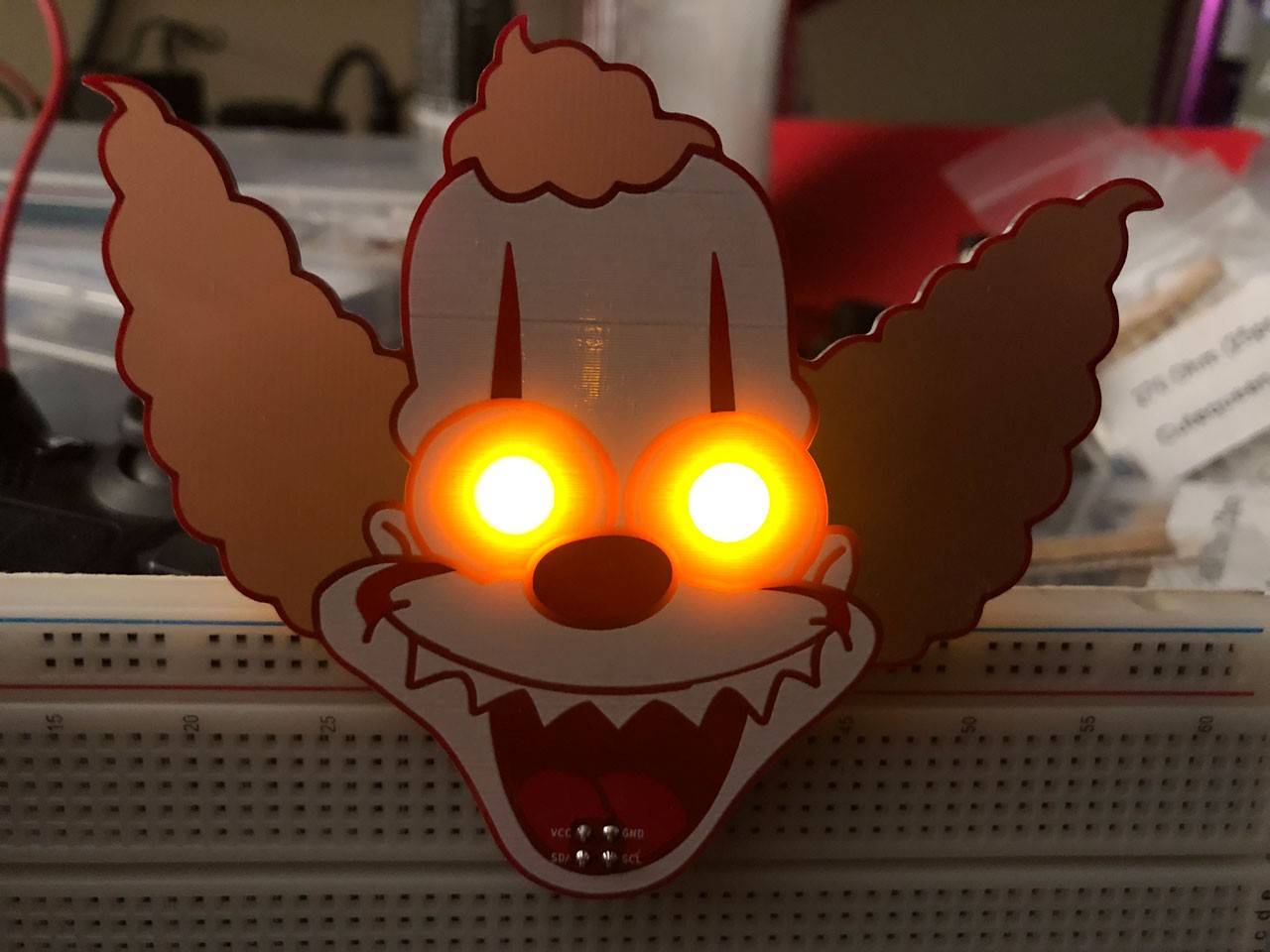
Krusty the It got a massive response on twitter. In a very short order I went from next to no followers to dozens of followers. Twitter has played a big part in my motivation to participate in Badge Life, there are few communities that are as great as the Twitter Badge Life community is. The response was so immense that I decided to order another 100 boards to supplement the original 50. This gave me the opportunity to make some minor tweaks and to order another SAO and save money on shipping.
The design of my SAOs are only made up of 4-5 Components. The original design was 2x LEDs, 1x Resistor, and 1x SAO Connector. When I found that the resistor dimmed the LEDs too much I removed it in the first board revision that I sent to the fab. This would prove to be one of many fuck ups.
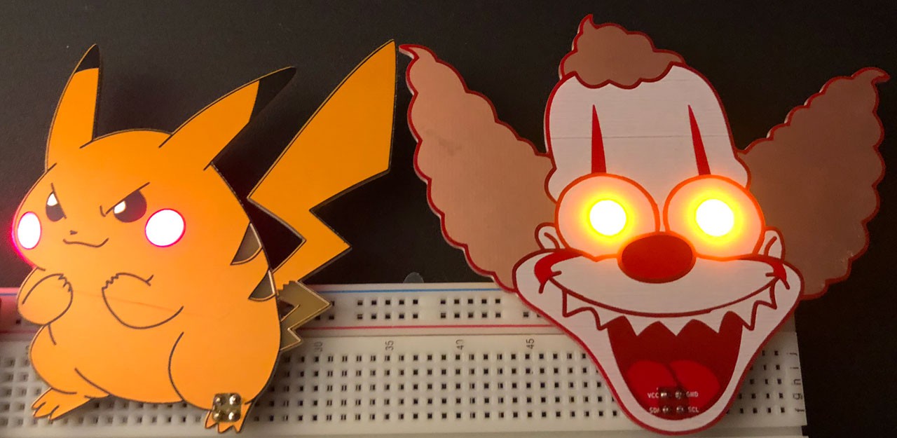
After I got my boards back from PCBWay I immediately soldered one together and shared it with the world at large on twitter. This would be the introduction of "Fat Pika". A kind friendly alternative to "Krusty the It" after getting feedback that many people loved Krusty but it would scare the shit out of their kids.
After getting Fat Pika in I moved forward with assembly of "Krusty the It". I personally soldered all of the boards over a weekend and shared my results with testing and prepping them to be packed for DEF CON. I was very excited and thrilled to be more than 1/2 way done with my SAO assembly efforts.
At this point I was floating on cloud 9. People loved the work I'd done and I had new followers on twitter every day. As it's creeping closer to DEF CON Badge Life posts are becoming more and more frequent, it just couldn't get any better! Eventually I joined a group of other Badge makers, most of which I knew of and looked up to I was very excited to be able to chat with an experienced group of badge makers. Life was fucking awesome.
What I Fucked Up
Once I joined the group and said my hellos I saw they had a channel for addons. I checked it out and to my surprise the last activity was about my Krusty assembly efforts! I knew some of them already knew who I was and really liked my work so I was really excited to see what others had to say! Unfortunately, what they were talking about was the orientation of my SAO Connectors.
They were looking at Krusty and trying to figure out if my silk screen labels were incorrect or if I had actually mistakenly rotated the SAO. My heart sunk. I immediately opened Kicad and checked my files and prayed that I just mishandled the labels and didn't fuck up the orientation.
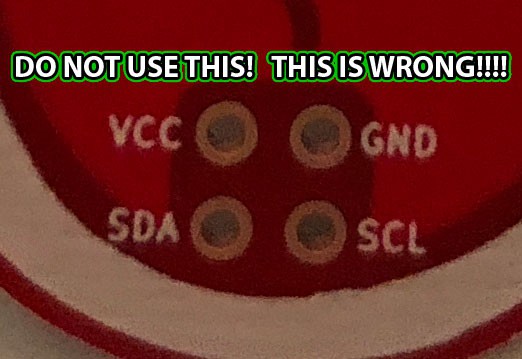
FFFFFFUUUUUUUUUUUUCK! I had in fact totally fucking botched the orientation of the SAO Connector. As soon as I looked at it in Kicad I immediately understood what went wrong.
So what went wrong here? In a nutshell. I use reverse mounted LEDs on my SAOs. In my case that means they're mounted to the back of the board. Since all of my components were on the back of the board I instinctively selected all of the components from the Net list and pressed "F" to flip them (and pay my respects of course). That meant I was already fucking up by flipping the SAO Connector.
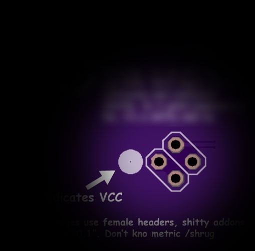
For some stupid reason when I was placing the SAO I was paying attention only to the circle indicator that was used to show where VCC was supposed to be if, for whatever fucking reason, the SAO Connector were rotated 45 Degrees. This gave me some kind of moronic tunnel vision that took me 2 Designs and 250 boards to catch. It didn't occur to me that the circle indicator was supposed to be on the FRONT of the board.
The Good News, The Bad News, and More Bad News
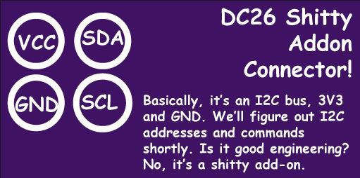
Okay, so my SAO Connectors were the incorrect orientation, but that's not the end of the world. The placement of the VCC Pin was still correct, only Ground was in the wrong position. I thought of a simple board I could have made that would bridge the incorrect pin with the correct Ground pin and then could snip off the wrong pin and continue on with life.
But upon closer examination of my board design the other makers started asking questions about my choice to eliminate the Resistor. Of course without the resistor the LEDs were wide open to the full power that the SAO was receiving. Normally this is bad, normally the LEDs can't handle a full 3.3 volts. With my prior tests with a CR2032 and another badge I did I found I didn't need the resistor in that design. Having a resistor dimmed the LEDs too much, destroying the effect I was looking for.
I had incorrectly assumed after seeing that the LED was too dim on the first SAO revision that it was no longer necessary in that one either since after all I had it hooked up to a 3.3v power supply and without the resistor I got what I was looking for.
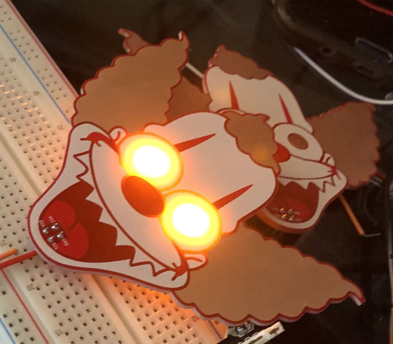
As it turned out I was wrong. It took a couple of hours, and buying a new Multimeter (I had literally just loaned out my good one two days earlier and apparently my spare was a piece of shit) but we figured out that my bread board power supply was only giving out 2v. It ultimately came down to the power brick I was using wasn't good enough so I remedied it, got the full 3.3v and holy fucking shit the LEDs were so bright it was literally painful to look at.
So now I have 150 SAOs that are assembled, most of which don't have a place for a resistor that they do in fact need, and another 100 SAOs that just arrived from the fab and are still wrapped up waiting for me to start assembly and none of them have a place for a resistor.
This was a massive fuck up.
What I Did Next
So now what I had to decide was whether or not I wanted to order a whole new set of boards, or make a board to patch the problem. Because I realized I couldn't make a patch board without having a second 2x2 Header I decided to scrap that idea for the time being and suck it up and correct my mistakes in Kicad, order replacements, and move on from there.
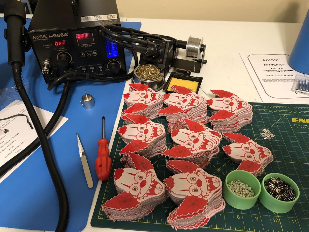
The next day I submitted my fixed gerbers to the fab and ordered 200 Krustys and another 100 Fat Pikas. The cost difference between 150 and 200 was such that I might as well order another 50 Krusty's. I then went to my local Microcenter and bought a Hotair Solder Rework station and began the process of desoldering the 300 LEDs and 150 2x2 Headers and attempt to recover them. In the end I recovered all of the LEDs and all but 2 of the headers. I also had to order another 50 SAOs worth of LEDs, headers, and finally 300 SAOs worth of resistors so I placed that order the same day.
With the order of the additional parts as far as I was concerned that was the conclusion of fixing the massive fuck ups that were found with both Krusty and Fat Pika.
What I'm Doing With 250 Reject Boards
So now I have about 250 reject boards to deal with. My friends on the community advised that I still sell them at a steeply discounted rate as is because a lot of people would still want them. I decided to take a step beyond that. Over the weekend I put together a board that would allow someone to make a functioning SAO out of the reject boards. It's simply called "SAO Fix".
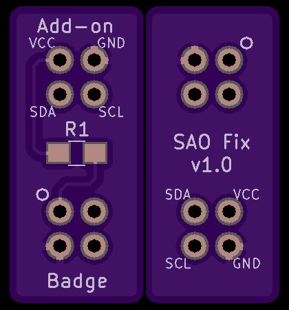
The SAO Fix addresses the issues that were found with my original Krusty & Fat Pika boards. With this you will be able to solder a necessary 0805 51ohm Resistor and another 2x2 header so that it can be properly mounted on a Indie Badge giving you a properly working Shitty Add-on. I've also made this file available to the public incase you read this and find that you too have made the same blunder. If you have made a similar blunder but not exactly the same the Kicad files are available for you to modify yourself to match your use case. As of the time of writing you can buy 3 boards for $1.70 from Oshpark. You can find the project page for the SAO Fix here.
What I Learned & Conclusion
- Double check your voltages.
- Don't assume that because it says 3.3v on the label, and you have it plugged up to the 3.3v channel, that it is actually 3.3v.
- Trust the math.
- I actually did know that the LEDs should have a resistor, the math I did before hand said as much but the math wasn't lining up with the real world results. This ultimately comes back to lessons learned #1.
- Always(!) have someone else double check your work!
- The only reason my ass was saved was because others spotted the issues. If it wasn't for their help I would have shown up to DC with at least 250 Shitty Add-ons that at best didn't work, at worst damaged other badges.
- Reach out to Indie Badge Makers and ask if they would be willing to review your work, more often than not they are willing to lend a hand.
- Don't Work in a Bubble.
- It's alright to be protective of your projects, but you can still talk to others and get multiple opinions about a situation. Had I shown early renderings to just a couple of people all of these problems could have been avoided and a lot of money would have been saved.
- Double, triple, quadruple check the spec!
- At least with the orientation of the connector if i hadn't gotten tunnel vision about the orientation of the circle I would have spotted that issue on my own. I can bitch and moan about shitty documentation and confusing diagrams all day but the truth is that when I brought the SAO Connector into Kicad it was already in the correct orientation. That fact is backed up by the bare bones documentation that was created, I just ignored it.
I know this was a long read and if you didn't skip ahead to the end I appreciate you taking the time to take it all in. I hope you will learn from my mistakes and apply them to not only your Badge Life projects but everything you do after.
Believe it or not despite the financial cost I considered the entire process invaluable. Often times the best way to learn is to fail and this massive failure has taught me even greater lessons.
Last, a special thanks to the following people for saving my ass:
- Supersat
- Hyr0n
- Hamster
- Zapp
- Krux
- Blenster
- ChrisGammell
- WBM
They saved my DEF CON this year.
Discussions
Become a Hackaday.io Member
Create an account to leave a comment. Already have an account? Log In.
It feels so good to see others fail! Thank you for learning things the hard way!
Are you sure? yes | no
I think a quick fix might be to cut the SDA pin you have labed GND and directly solder a resistor between between that pad and the actual GND pin you have labeled SDA. I think an 1/8 watt through hole resistor would fit and work nicely without being too visually objectional.
Are you sure? yes | no
Dude, I feel you! I had small errors in some layouts exactly because of the reasons you stated.Double and triple check connections. Have a day or two between checks and don't do it in a hassle just to get your boards quick.Thanks for your write-up!
BTW: another board, another fail. It still happens, god damn: https://hackaday.io/project/78326-upower-beehive-sd-logger/log/147700-new-v12-boards-arrived
You're not alone!
Are you sure? yes | no
These things happen to all of us; keep your head up and don't be ashamed of a solid learning experience. Glad you documented the issue and your fixes. And excellent SAO designs!!
Are you sure? yes | no
Oh no :o
Immediately after the announcement of the shitty addon standard, I was strongly considering launching a standard called "shitty addon NEXT GEN" with an identical footprint, but VCC and GND flipped. You should do that and promote it as well as possible :D
Are you sure? yes | no