danjovic wrote 06/08/2018 at 00:43
• 16 likes
• 2 min read
• Like
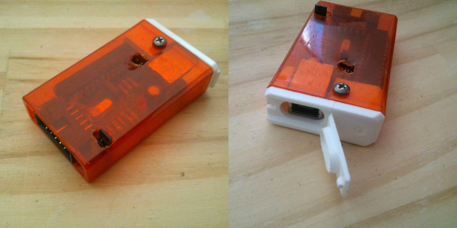
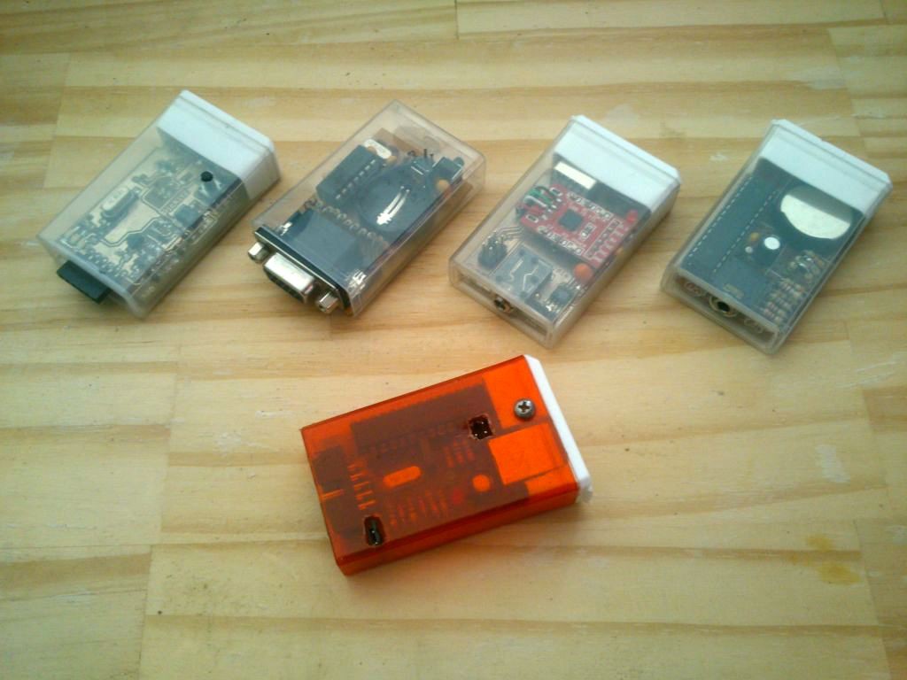
My collection of homemade projects stuffed inside Tic Tac boxes.
From left to right: Pickit2 clone, USBAsp, TicTacX, Arinc429 Sniffer, 32 Shades of GreyPICKit2 cloneUSBAsp Tic Tac XArinc 429 sniffer/analyzer32 Shades of GreyAnother view of the collection
@danjovic , thanks for all your projects. Does this device take 2XCR2016 coin cell batteries, totaling up to 6V in order to operate? Will that kill the PIC16F688? Wait...The 4004 diode will have a 1V drop then. That will then be safe for the PIC16F688?
I made one, the one right under the USBasp photo[1], with only one 3V coin cell battery installed. I read your github page, and, after fumbling for awhile, I realized that I have to supply the 5V+ input into the 5V/GND header pins to make it show the VGA pattern on my VGA monitor. Then I pressed the button 8 times to cycle back to the VGA mode, and the signal is lost! I had to unplug then plug back the 5V supply to its display the VGA pattern again. Not sure why. Maybe because I only have one coin cell battery and ALSO supply the 5V DC input?
The 5V indicated in in schematics are only the "name" of the voltage rail after the diode. The circuit shall be powered solely by the two 2016 batteries stacked to get 6Volts. The diode provide enough drop for the PIC to operate in safe area. Be sure that the battery socket is not short circuiting one of the batteries (measure the voltage across the VDD and VSS pins of the PIC to confirm that.
Some monitors may get lost when they receive signals that they do not support.
@danjovic Thanks for the reply. Ok, I know have two CR2016 batteries connected in series to provide 6-6.3V. So, just to be safe, I take out my PIC16F688 chip, and I short the jumper to have 5V flow to the circuit after the 4004 diode. Then I measure the VCC and GND pins of the traces on the board to the PIC's VCC and GND pins. It shows that have 6.3V actually but not 5V to the PIC16F688. So, I am not sure if I should put the PIC in??? Thanks again!
 danjovic


Discussions
Become a Hackaday.io Member
Create an account to leave a comment. Already have an account? Log In.
@danjovic , thanks for all your projects. Does this device take 2XCR2016 coin cell batteries, totaling up to 6V in order to operate? Will that kill the PIC16F688? Wait...The 4004 diode will have a 1V drop then. That will then be safe for the PIC16F688?
I made one, the one right under the USBasp photo[1], with only one 3V coin cell battery installed. I read your github page, and, after fumbling for awhile, I realized that I have to supply the 5V+ input into the 5V/GND header pins to make it show the VGA pattern on my VGA monitor. Then I pressed the button 8 times to cycle back to the VGA mode, and the signal is lost! I had to unplug then plug back the 5V supply to its display the VGA pattern again. Not sure why. Maybe because I only have one coin cell battery and ALSO supply the 5V DC input?
[1] https://cdn.hackaday.io/images/4261861528418080778.jpg
Are you sure? yes | no
You welcome, pal.
The 5V indicated in in schematics are only the "name" of the voltage rail after the diode. The circuit shall be powered solely by the two 2016 batteries stacked to get 6Volts. The diode provide enough drop for the PIC to operate in safe area. Be sure that the battery socket is not short circuiting one of the batteries (measure the voltage across the VDD and VSS pins of the PIC to confirm that.
Some monitors may get lost when they receive signals that they do not support.
Are you sure? yes | no
@danjovic Thanks for the reply. Ok, I know have two CR2016 batteries connected in series to provide 6-6.3V. So, just to be safe, I take out my PIC16F688 chip, and I short the jumper to have 5V flow to the circuit after the 4004 diode. Then I measure the VCC and GND pins of the traces on the board to the PIC's VCC and GND pins. It shows that have 6.3V actually but not 5V to the PIC16F688. So, I am not sure if I should put the PIC in??? Thanks again!
Are you sure? yes | no
Neat idea. When Altoids Tins are just too big. :)
Are you sure? yes | no
Good idea ! I do like :)
Are you sure? yes | no
So... You have fresh breath and fresh thoughts... :D
Are you sure? yes | no
Sure!!! lol!!!!!
Are you sure? yes | no
very awesomely executed man!!!
Are you sure? yes | no
Thanks!
Are you sure? yes | no