 Yann Guidon / YGDES
DISCLAIMER: I have no stable enough frequency source so the accuracy and stability are not tested here.
2 years ago, I have bought 3 of these crystal oscillators from eBay :
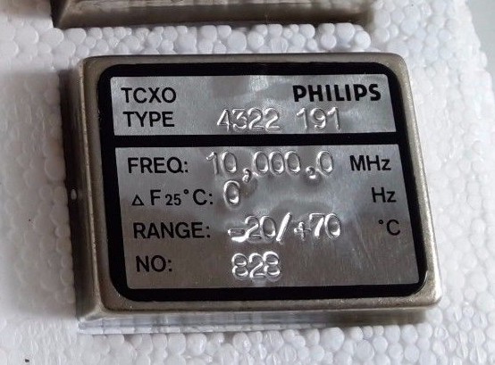
(picture courtesy of the seller bg2014-manue, thanks for the cross-linking !)
In theory, if the frequency drifts by less than 1Hz at 10MHz, that's in the ballpark of 0.1ppm (or 100ppb ?) but without a proper equipment, I can't validate the frequency accuracy and stability. I'm trying to solve this for a long time, if you remember my burned Rb oscillator :-D
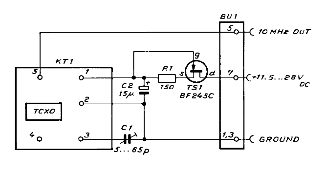
I think these Philips modules are a good compromise for price/performance/ease of use. Only recently did I test them so I went google-surfing. I could only find partial information but cross-checking different sources gave me some confidence about the pinout. For example the document "Frequentie standaard" by PA0WSO (in Dutch) gives a good example of how to use the module but the pinout is not defined.
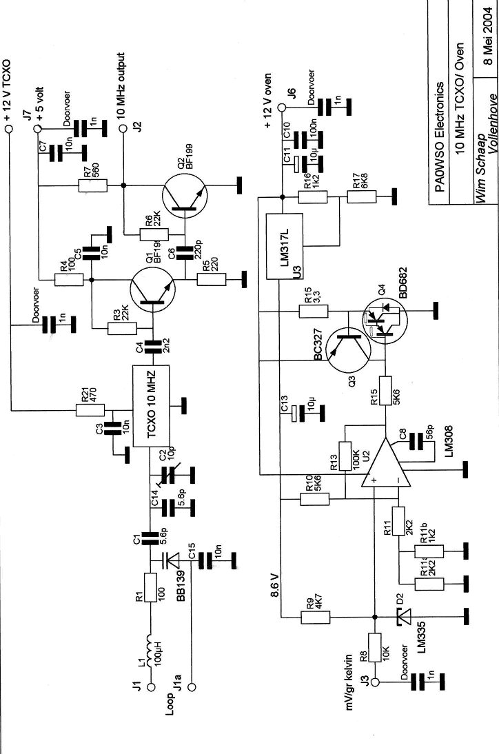
The right hand half shows the temperature compensation, using a resistive element. A TEC could be used instead if ambient temperature rises above 25°C. The lower left quadrant shows the varicap control for tuning/"pulling" the oscillator.
Another useful document "A 10 MHz Timebase Clock for Frequency Counters - complete with a PLL for DCF77" shows the pinout but it might not apply to this variant : apparently there are several permutations but as long as you get the right VCC, GND and voltage, you can probe the pins with an oscilloscope.
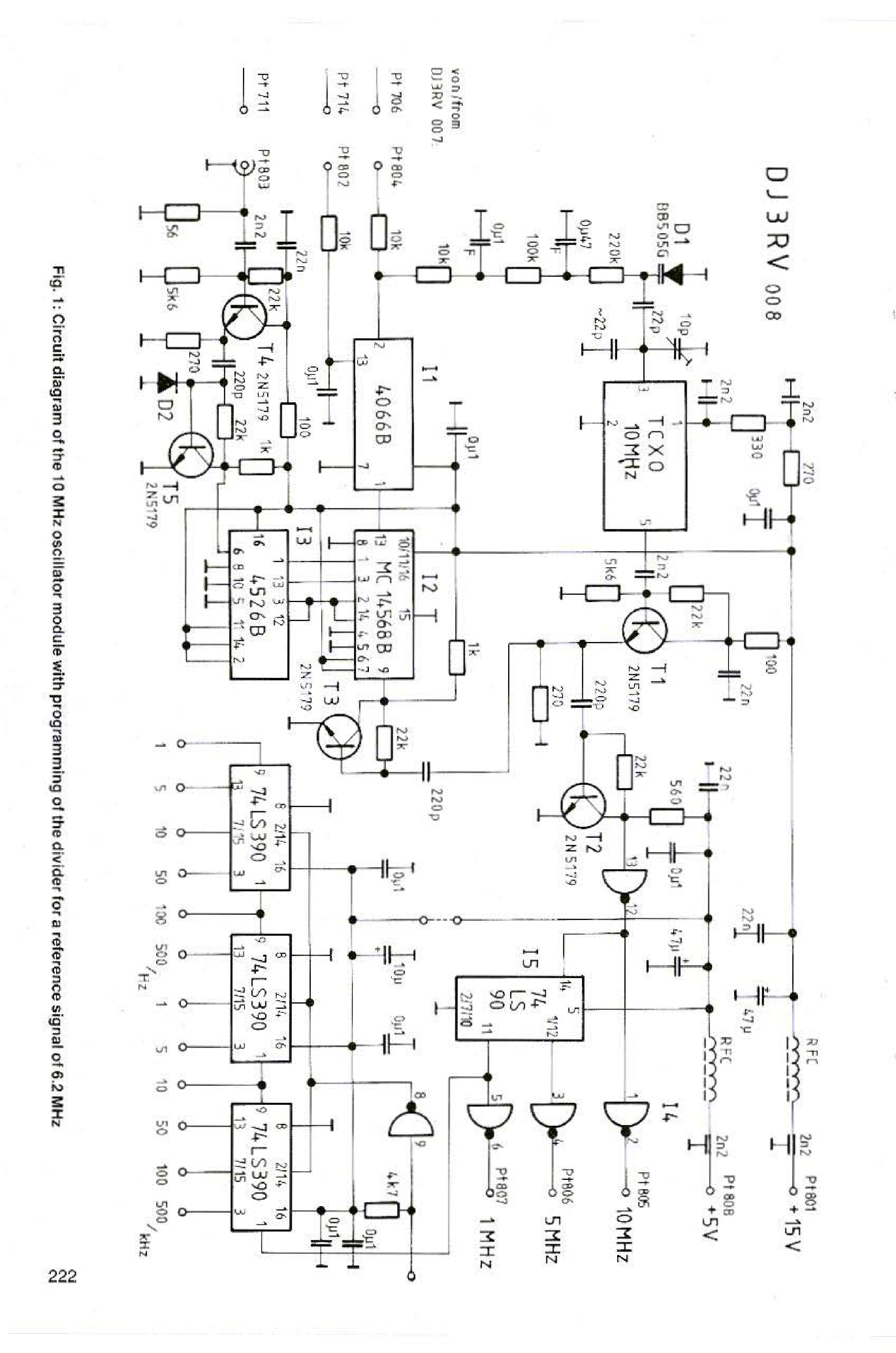
If you get the pinout right, these 2 application documents help with the design of the pulling and amplification of the output.
A forum page shows the following pinout :
The assignation is correct BUT my specific model is not "pulled" by a resistor, but with added capacitance.
Luckily, Philips has used these modules in their own lab devices (PM6670 and PM6672) and they appear in the service manual :-) The above forum page provides the .djv file, along with other measurements. The TCXO is mounted on optional module PM9678B
WHY would the use a poor BF245 to handle 60mA ??? And here, the adjustment cap is on another pin...
The rest of the service manual shows the amplification but there is no heat management.
(if you find more references, I'll be happy to include them. I remember seeing a catalog/datasheet that shows the various pinouts and options but not it evades me)
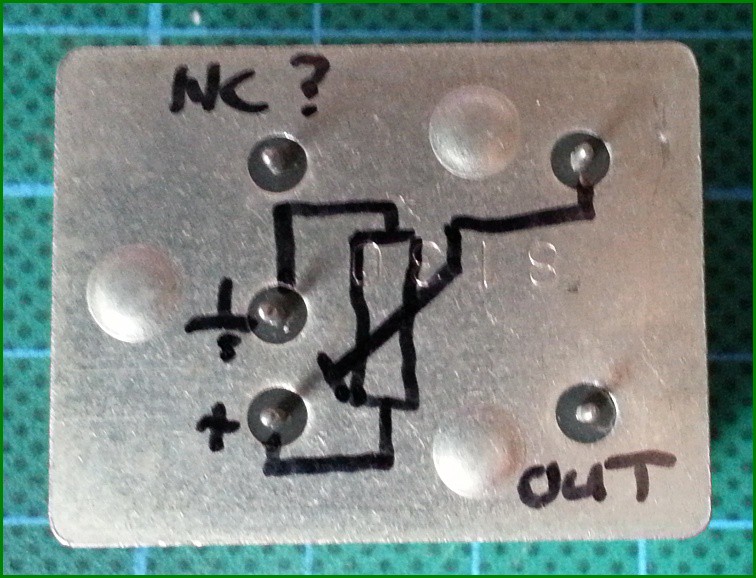
I measured a few things that I write down here. But first here is my pinout diagram for this specific model :
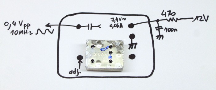
Don't connect the other pins.
- 0V : just the ground.
- Vcc : I don't know why there is a resistor. Maybe there is an internal shunt regulator but since the current increases with voltage, I doubt... The doc recommends 470 Ohms and 12V, but the 60mA drops the input to about 7.4V. I suppose these values will change with temperature, input ripple, and whatnot... Generous decoupling is recommended (ceramic+electrolytic ?).
- The output: the 'scope shows it's 0V-centered, meaning there is an internal capacitive coupling. I also noticed the frequency slightly varying depending on output capacitance or impedance, I'm not sure... The amplitude is weak, buffer it with a high impedance amplifier (JFET input ?).
- There is another pin for adjustment, also called I.C. on some models. In this specific model, this is a capacitive pulling. I observe a lower voltage version of the output, don't touch this pin or you'll detune it... NOTE: FREQUENCY ADJUSTMENT IS NOT TESTED YET.
Here is how I quickly tested the CTXO :
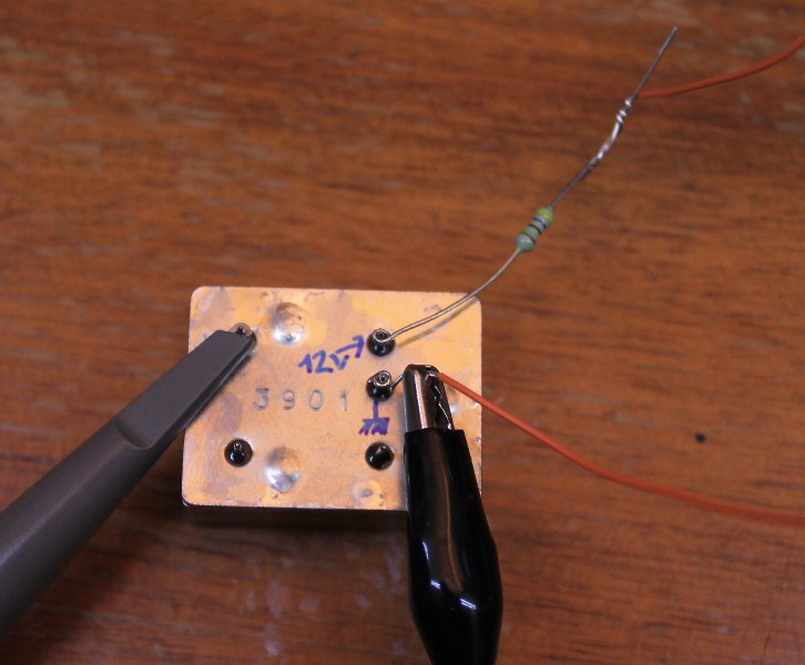
Yes it's ugly but enough to check that it works :-)
When displayed on the 2467:
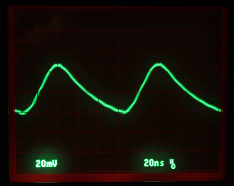
Here it's using a 10x setting for the probe so we might infer about 400 or 500mVpp. The amplitude and waveform vary significantly when using the 1x probe so impendance matters !
Looking with the DSO : amplitude is coherent and frequency about right despite the noise.
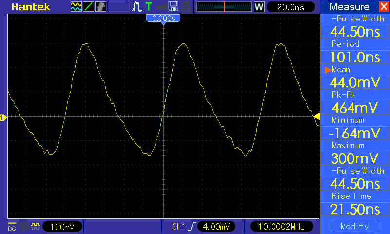
I did all these measurements without caring too much about signal integrity or decoupling. Due to the 10x impedance and the high frequency, low level signals, there is significant noise picked up from the environment by the probe.
There is also a notable variation of frequency depending on the output load so it might be used to "pull" or adjust the frequency, in addition to the adjustment pin. You'll have to make your own amplifier because this is NOT able to drive 50 ohms and the amplitude is quite weak.
I have not waited and thermal equilibrium might not be reached. The DSO has shown variations of a few hundreds of Hz but this might be caused by its own cheap design and the warm-up time. These Philips modules are specified as "0Hz" (around 0.1ppm ?) at 25°C but there is no oven and no external temperature feedback is available to drive an external heater/oven.
Pros:
Affordable, good quality, quick startup, reasonable power consumption (works when fed with 4 or 5V but that might detune it), crystal is pre-aged (lower long-term drift)
Cons:
a bit bulky compared to typical canned oscillator, yet it's not a fully integrated solution: you'll have to build external circuits and care about the output impedance, the ambient temperature, the power supply stability...
Overall:
These are useful oscillators that shouldn't detune too much, yet are still sensitive to external factors so it's not a viable frequency reference on its own and can't replace a proper calibrated ovenised oscillator, a Rb source or a GPS receiver.
These modules were intended to be integrated in lab equipment of medium quality, better than the cheap Xtal osc that is often off by 50ppm and literally "drifts with the wind" (like my chinese DSO ?), but where it's not economical or justified to use a more precise system (that would draw more current: 20× more for an oven or a Rb chamber). With proper tuning, I suppose it can operate at around 5V.
The whole system (when integrated with amplifier and eventual heater) should be re-tuned with the help of a much more stable equipment but it's "good enough" to tune my lower-grade oscillators. It's also a good candidate for a low-power GPS-DO, as shown in the applications I linked above.
I hope to find a better solution to my frequency reference issues but I can't use GPS in my building :-/
Discussions
Become a Hackaday.io Member
Create an account to leave a comment. Already have an account? Log In.
Many years ago a fellow student derived a frequency reference from the DCF77 77.5 kHz transmitter with the help of a slow PLL. It seemed to be sufficient for testing temperature stabilized crystal oscillators...
Are you sure? yes | no
RF reception in my building is abyssal... I would have to install a mast and run a looong antenna cable, with all the potential "human, animal and atmospheric degradations". This metrology struggle is not recent :-D
Are you sure? yes | no
DCF77 might still work (I mean all those €7,99 radio controlled clocks do work in a basement room more often than not , right?).
Are you sure? yes | no
The emitter is far, far away and radio propagation is affected by clouds etc. so the short term and long term stability are good but not medium term... GPS would be perfect but far from easy in my very specific case. But constraint is mother of invention right ?
Are you sure? yes | no
That's also how I see it :-)
By the way, atmospheric disturbances will ruin short term stability but long term stability (~10s) should be good to very good. I still remember how the frequency of a temperature controlled crystal oscillator swayed when opening a window. The PLL was locked to DCF77, and there is just no way to explain how the PLL could have caused that ;-)
Are you sure? yes | no
I am sure I am incorrect but when I see 10,000.0 MHz I am thinking 10 GHz :-)
Are you sure? yes | no
yeah you gotta be cautious, it would require totally different gears...
Are you sure? yes | no