 Frank Buss
5 V to 3.3 V
Test circuit with a SN74AHC125N, bought here, for the 5 V to 3.3 V level translation:
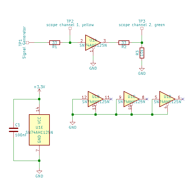
Signal generator: Siglent SDG1050, 50 MHz max output frequency
Oscilloscope: Agilent DSO-X 3012A, 100 MHz analog bandwith, 4 GSa/s samplerate
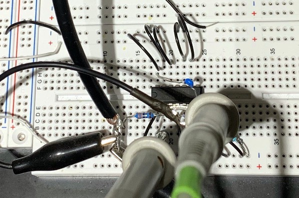
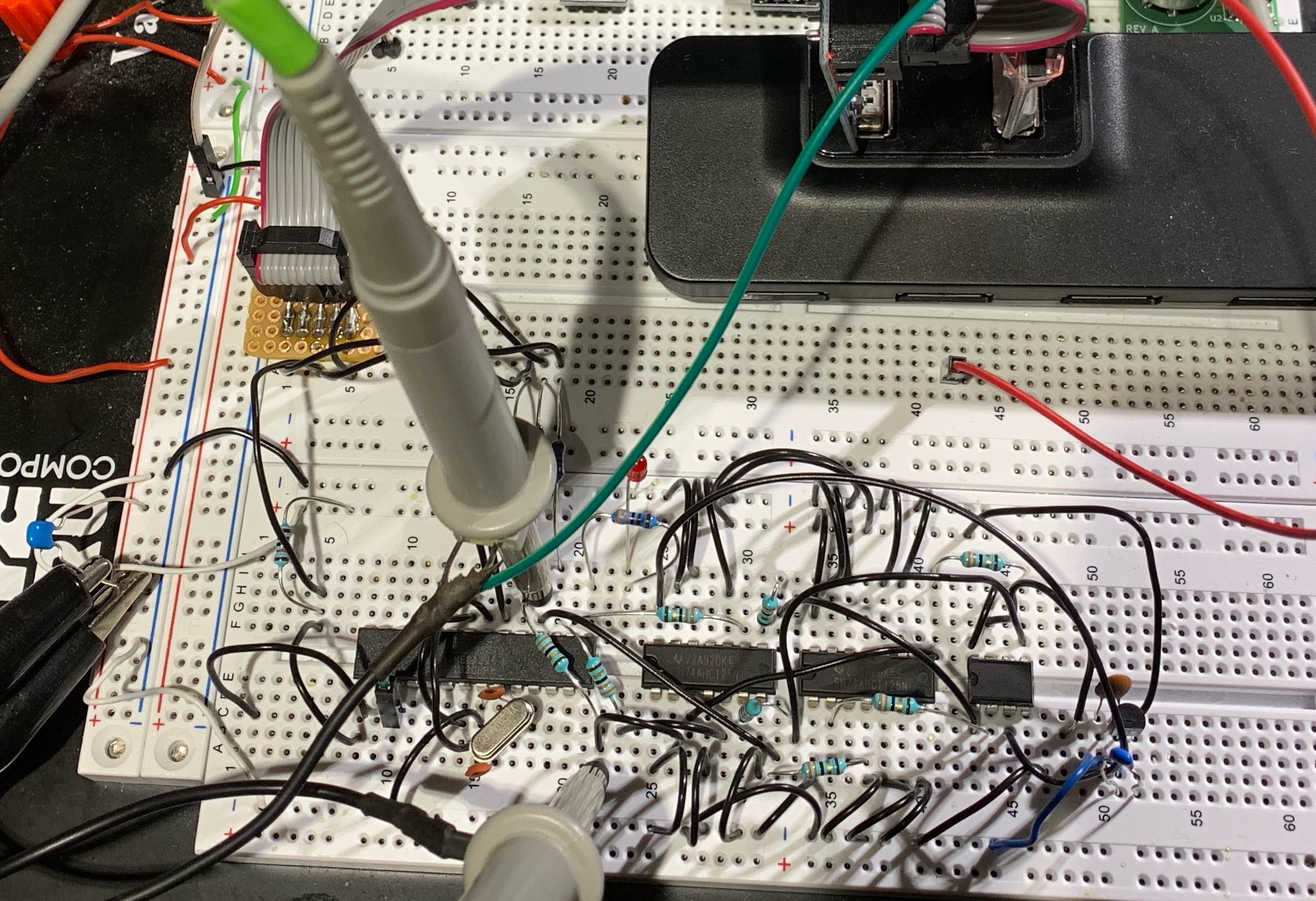
Test setup:
Result for 10 MHz:
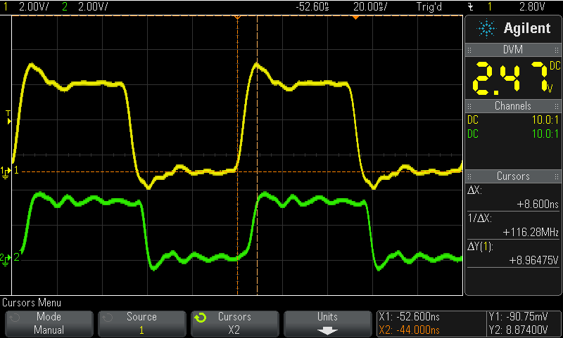
Less than 10 ns propagation delay, fast edges.
3.3 V to 5 V
Result for a SN74AHCT125N, bought here, same circuit and test setup, but with 5 V supply for the buffer and 3.3 V for the signal generator, to test the 3.3 V to 5 V level translation:
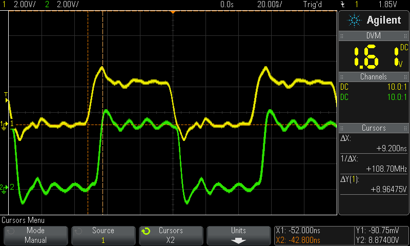
A little bit slower, but still less than 10 ns propagation time and fast edges. The datasheet guarantees high level signal detection down to 3 V, but it works even with 2 V:
Test with a CD74HC04E hex inverter
Test circuit with a CD74HC04E, bought here:
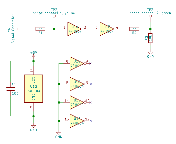
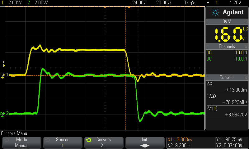
Doesn't work with 2 V for the input signal and gate propagation time is longer than 10 ns. With 3.3 V at the input and 5 V for the supply it looks like this:
Fully working example with FRAM
This is an example with the SN74AHC125N and SN74AHCT125N, and an ATmega328 and a FRAM chip. The ATmega328 is running a 5 V, and the memory with SPI port at 3.3 V. Test setup:
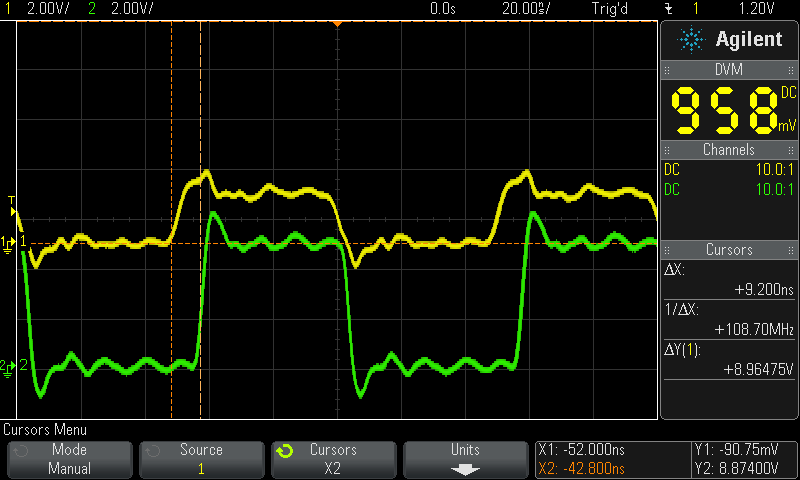
The SPI bus is running at the max possible frequency of 10 MHz. Yellow is the clock signal from the microcontroller and green the MISO signal from the memory, measured at the microcontroller input:
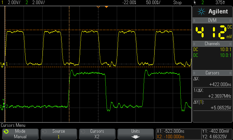
The combined delay of the memory IC and the gate delays of the voltage translators is less than 20 ns, good enough that the microcontroller can cleanly sample the MISO signal at rising clock edge.
Discussions
Become a Hackaday.io Member
Create an account to leave a comment. Already have an account? Log In.