 Patrick
Two things:
- I can’t believe this worked (almost the very first time) !
- I’m surprised nobody else seems to have done this before !
OK. I have been looking for months on the net for somebody, anybody, who has combined WS2812b addressable LED’s with switches to create a switch array. At the end of this I explain why I would want such a thing, but for now just please understand that I could not find any other examples of anyone selling, or even trying, something, like this.
Perhaps no-one needs it, or perhaps it exists, but is just not on the web, but perhaps no one has thought of it before. In any case, it seemed to me that it would be fairly straightforward to combine a switch with each ws2812 in an array (or a strip), and be able to tell which button is pressed, if any, based on the timing of the signals being sent to the LED’s.
Now please understand that this is very crude hardware and code. I didn’t even expect it to work. The LEDs are supposed to have capacitors from power to ground, most schematics recommend a resistor from the output pin of the Teensy to the input pin of the LED, and I’m pretty sure that no electrical engineer out there would recommend hooking the DIN (data in) pin of each LED through only a switch directly to a bus line to an input pin on the Teensy. Something has to fail, right? Oh, and always use a separate power supply for the ws2812’s lol 😊
So, please let me say that I will appreciate any comments, or contributors, that can design a proper circuit, help me to understand how it should work, and/or really want to dig in to write good code for this purpose.
CIRCUIT BOARD
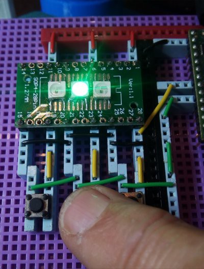
I have a couple of ws2812 arrays sitting around (an 8x32 and a 4x4), but I don’t have any strips. That’s a shame because the strips look like you can easily cut one off and work with it. You probably have a strip you can just cut up! I don’t want to cut up the arrays, but I do happen to have a bunch bare ws2812 LEDs that I bought experiment with. So I rummaged through my stuff and found a little circuit board I could solder them to. That being about my third try to air-solder SMD’s, I glued them on with superglue, a little too much in one place, and then glommed some paste solder on em with a toothpick, and blew hot air on em. Even though it was only 215C, I basically tortured the LEDs as I had to burn through the superglue on one of the contacts. Nonetheless, they conduct electricity, and there are no shorts.
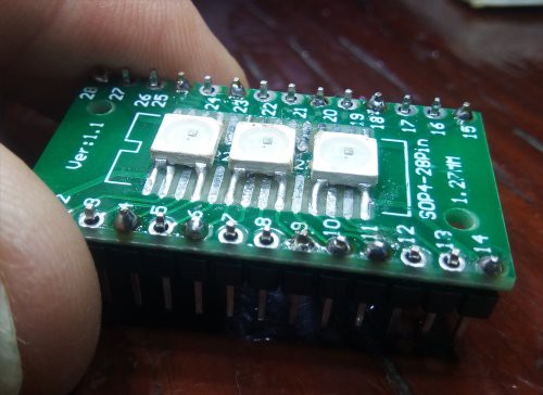
I added some pins to the board, so then I had three ws2812’s I could play with on a breadboard. If you want to build one of these, you probably can just cut one off a strip and use alligator clips or whatever it takes to hook them up.
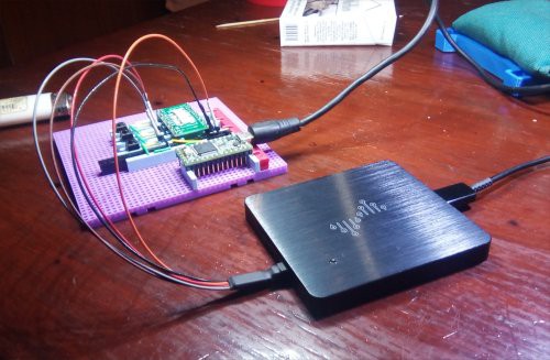
The first circuit I made used jumper wires. Much to my surprise I hooked up the 5V and ground and got the Teensy example basic ws2812 test program working with my little 1x3 array of LEDS in a few minutes,.
So then I decided to try to write some code to make it work as a switch array.
THEORY OF OPERATION
As you send serial data to the LEDS (actually, to the first LED’s DIN – data in - pin) using the ws2812 protocol, each LED takes 24 bits to display an RGB value. OK, actually it’s GRB, but that’s not important!
After the first LED “eats” the first 24 bits, it starts passing the remaining bits onto the next LED. So the second LED does not see any bits (rising edges) until the first LED is done with those first 24 bits. Then the second LED “eats” the second 24 bits before it starts passing the remaining bits to the third LED, and so on.
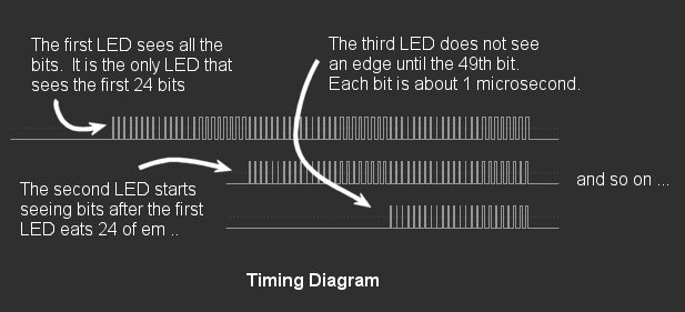
The other thing worth knowing is that each bit in the ws2812 protocol, both ones and zeros, has a HIGH and a LOW part. So, even if you send all 0’s to the LED’s, and don’t turn any of them on, you still send 24 rising EDGES to each LED.
What is interesting about all this is that it provides each LED with a unique timing signal.
If we then connect all the DIN pins from each LED, through switches, to a common wire, and we hook that wire up to a single digital input on the Teensy, we can tell WHICH BUTTON is pressed, if any.
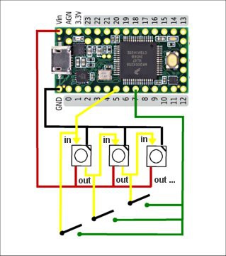
More precisely we can determine the FIRST (lowest numbered) button that is pressed, or if none is pressed. This initial circuit/algorithm cannot detect multiple simultaneous presses but I believe with the addition of a minimal amount of hardware, it could.
Before we start writing the “frame” of all three pixels, we set a variable for the “current button” to zero. Then just after we write the HIGH rising edge for each bit, we check whether or not there is a corresponding HIGH on the input wire. If there is, and it is the first HIGH we have sensed during this “frame”, then we know that it must be the switch associated with the LED we happen to be writing the bit to.
BAD CRUDE CODE WORKS lol
Although we *could* just check once per LED (per pixel), and a lot of work could be done to make the timing more precise, and the code more efficient, perhaps even using DMA, I just rammed together some bitbang code to write to the LED’s, got that barely working, and then stuffed some digitalReads() into the sendPixel() method to see if anything would work.
When it sort-of-worked the very first time, I was so pleased I decided to make a better breadboard circuit, take some pictures, and post this page so others could see it.
Here’s the whole stupid program. It is (has to be) specific to the Teensy 3.2 as it has absolutely no sophistication or precise timing. It just happens to work with the delays I stumbled upon. Oh, and as I’m using the serial port, I have to turn interrupts off and back on around the writes.
#define LED_PIN 5
#define SWITCH_PIN 7

 // Neopixel wants colors in green then red then blue order

#define RED    0x001600
#define GREEN  0x160000
#define BLUE   0x000016
#define YELLOW 0x141000
#define PINK   0x001209
#define ORANGE 0x041000
#define WHITE  0x201020

int button_pressed = 0;

void sendBit(int button_num, uint32_t bit)
{
    int pressed = button_pressed;
    if (bit)
    {
        digitalWriteFast(LED_PIN,1);
        delayMicroseconds(1);
        pressed = digitalReadFast(SWITCH_PIN);
    }
    else
    {
        volatile int i;
        digitalWriteFast(LED_PIN,1);
        for (i=0; i<2; i++);
        pressed = digitalReadFast(SWITCH_PIN);
        digitalWriteFast(LED_PIN,0);
        for (i=0; i<4; i++);
    }
    digitalWriteFast(LED_PIN,0);
    if (pressed && !button_pressed)
        button_pressed = button_num;
    delayMicroseconds(1);
}


void sendPixel(int button_num, uint32_t data)
{
    for (int i=23; i>=0; i--)
    {
        sendBit(button_num, data & (1<<i));
    }
}


void showLeds()
{
    delayMicroseconds(9);
}


void setup()
{
    Serial.begin(115200);
    delay(1000);
    Serial.println("started...");
    pinMode(LED_PIN,OUTPUT);
    pinMode(SWITCH_PIN,INPUT_PULLDOWN);

}


void loop()
{
    button_pressed = 0;
    static int counter = 0;
    static int last_button = 0;

    cli();
    sendPixel(1, last_button == 1 ? RED : 0);
    sendPixel(2, last_button == 2 ? GREEN : 0);
    sendPixel(3, last_button == 3 ? BLUE : 0);
    showLeds();
    sei();

    counter++;

    if (button_pressed != last_button)
    {
        Serial.print(counter);
        Serial.print(" ");
        Serial.println(button_pressed);
        last_button = button_pressed;
    }

    delay(30);
}
WHY DO I WANT THIS?
Thanks for asking!
What I’d like is a lightweight, flexible, mouse-pad-display for my feet (that is probably also a MIDI controller), that I could just whip out of my pocket, unfurl (or unroll) breezily onto the floor and plug it in, where it would then draw a control surface on itself consisting of buttons, sliders, and so on, so that I could control my guitar effects, looper, and synthesizer, with my feet, as I do now through 4 expression pedals, a Softstep2 AND an Akai MPD218, but as a single control surface without all connectors, usb hubs, and complexity.
I’d probably keep an expression pedal (i.e. for wah-wah) cuz I’m used to using it after 40+ years.
But I believe, for example, the current notion of a volume pedal is just a rotten idea.
You can only move your foot about 2 inches with volume pedals and it is not a particularly ergonimic motion to begin with. It is not accurate, nor repeatable, enough to control a Logarithmic volume scale, in my opinion. Volume pedals, and the big shiny push buttons are a legacy of the 1950’s … that’s not even “man on the moon” kind of stuff.
But surprisingly, you cannot just go out and buy a mouse-foot-pad, much less one with a rudimentary display capability as well.
Just talking about the ergonomics, with a mouse-foot-pad, I could have 10 or more inches of movement with a slider for the volume … to say nothing of swipe gestures and scrolling, which is what we normally, commonly do, and everyone understands as a way to deal with logarithmic scales.
I’m also experimenting with gyros and accelerometers in the same vein. Even better than a mouse-foot-pad would be no mouse-foot-pad! But those experiments are revealing that it is hard to get your bearings in gyro-accel-space and to keep them. Infrared sensors are another thing. Time of flight sensors are another thing. Lots of room for virtual sensing, but always have to stay aware of what would be practical to setup and teardown 4 nights a week at 1:00am.
This is for a gig, so the best thing would be if I could just unroll a 2 ounce dohicky on the floor. Also interesting are those “rollup” silicon keyboards that are cheap because the are ubiquitous, but if I want a mouse-foot-pad, I’d have to tool up the silicon at a cost of $10K and 5000 units to be practical, and sensor arrays also include a bunch of other hardware (multiplexers).
I’m also playing around with sewables, and 3D printed circuits, but thus far nothing has come as close to seeming like an actual idea as this ws2812 experiment. Taking advantage of the existing (actually complicated) circuitry on this LED is very interesting.
IMPROVEMENTS (ideas)
In order to sense multiple simultaneous presses, perhaps something could be done to gate, or latch, or otherwise “turn off” the output from a button once it has been sent.
Perhaps you have an idea how that could be done? It be nice if it could be done with one 2-pin SMD component (uhm, a capacitor somehow?). That would probably also make you a person who could design a (flexible?) circuit board for the whole thing. Of course, it should be designed as “cells” that can be repeated ad-infinitum and/or arrayed arbitrarily.
Get back to me on that, ok?
😊 We would also probably only want to do one digitalRead() for each pixel. It is only sheer laziness that had me do one per bit …
It’d be super cool to be able to 3D print, somehow, a transparent switch right on top of the ws2812. Perhaps with clear TPU? Or maybe DIY silicon injection molding? Or 3D print the circuit itself (i.e. Protopasta Conductive Filament).
Has anybody thought of sending solder paste through a 3D printer? The stuff I used today melts at 187C … well under PLA … you could probably put actual melted solder down as a stream onto some higher temperature plastic (ABS++) ….
CLOSING
Anyways, this was a fun one. I was so pleased I just had to get it up on hackaday right away !
I hope you have enjoyed reading this half as much as I enjoyed that moment when I pressed button number 2 and it worked!
Patrick
Discussions
Become a Hackaday.io Member
Create an account to leave a comment. Already have an account? Log In.
and these interesting https://www.ebay.com/itm/WS2812B-2020SMD-RGB-LED-Matrix-Panel-576Pixels-18x32-5V-Individually-Addressable/362681458444 because they have holes where a sensor of some kind could go
Are you sure? yes | no
also thinking about these https://www.ebay.com/itm/LED-Matrix-Screen-module-P3-RGB-pixel-panel-HD-video-display-64x32dot-192x96mm/273869267151?redirect=mobile and maybe somehow optically detecting where my toe is, and if/when it touches ...
Are you sure? yes | no
how can I create/buy a transparent touch sensor array with similar resolution that can go on top of something like this? Also thinking about accel/gyro/infrared sensors strapped to my foot :-)
Are you sure? yes | no
But maybe you do want to sense multiple switch depressions as this is the complete state of the switch array and sort out the semantics in software. I don't see the need to suppress interrupts if the CPU is fast enough.
Are you sure? yes | no
any idea how I might do that within this concept? I would like an array with 100's to 1000's of switches (resolution) or some other practical way to make a decent resolution footpad/display .. that doesn't involve putting a glass screen on the floor, faceup, in a bar-room ??
Are you sure? yes | no
Maybe throw in many cheap small 8 pin microcontrollers to condense the data stream?
To amplify, when you have lots and lots of pins, instead of a few in your prototype, connected to switches then the wiring to the input pin may present a lot of capacitance. The LED drive is a sort of distributed topology so perhaps you need the same for collecting input.
Are you sure? yes | no
actually the github presentation at https://github.com/phorton1/projects-ws2812bSwitchArray1 is better than the hackaday page ....
Are you sure? yes | no
@Ken Yap .. Uhm I think you may have kind of missed the point, but thanks nonetheless for answering. Yes I am aware of traditional scanned led and switch arrays ... with x-y grids. The tm1637/1638 are completely off base for what I'm getting at here. Those are specific led segment drivers with a built in multiplexer for a separate switch array.
My goal here, kind of, is to take advantage of the already existing multiplexing with the ws8211's built into the LEDs. You'll notice (a) I only use one gpio pin, (b) there are no multiplexers or additional hardware, and (c) there is no x-y grid of wires to the switches.
Please see the updated project at https://hackaday.io/project/167696-one-wire-3d-printed-ws2812b-switch-array
I DID notice that it is wrong to hook all the dins together. If you press two buttons at once you short circuit the bit stream. A diode at each switch should solve that problem, but i still can't figure out how i would differentiate two simultaneous button presses.
Are you sure? yes | no
If you are asking whether a scanned LED array can also serve as a switch scanner, then yes, this is the way it has been done since the days of one-chip calculators, to save pins. In that scheme the digit outputs also feed a keyboard matrix which connect to keyboard input lines. Nowadays you can get serial input chips that drive a LED matrix and also sense push buttons. Take a look at something like the TM1637 or TM1638.
If you are asking if there are ready made chip solutions using the WS2812 protocol, I don't know.
Are you sure? yes | no