LDR SENSOR:-
INTRODUCTION:-
LDR sensor is a type of resistor is variable and dependent on light of the surroundings. You can see these types of sensors in smart lights street lights and various other electronic gadgets which work in day time or in night or according to the light of the surrounding. These types of sensors are easy to operate and can easily be programmed to get output.
As this sensor is sensitive of small amount of light also it is used in various devices which are light sensitive. The sensor is very simple cheap and the basic one available in the market.
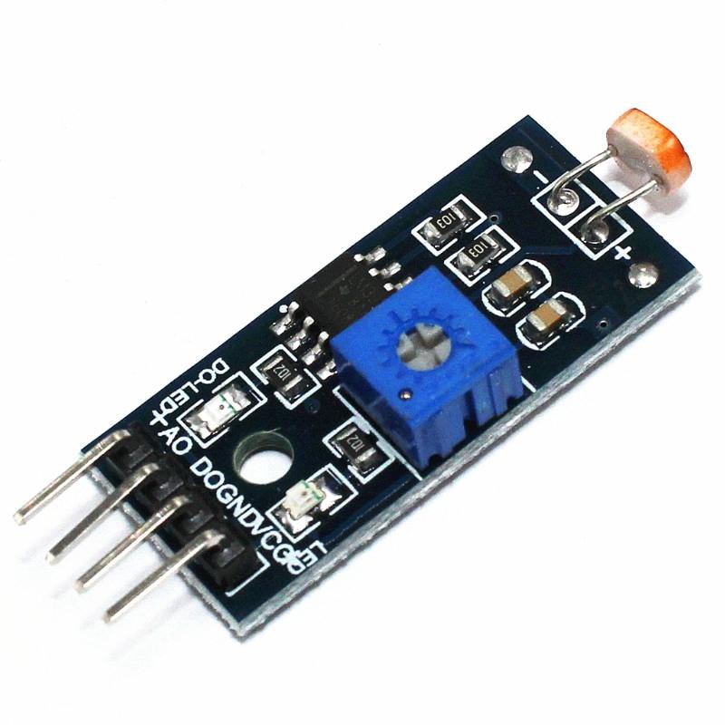
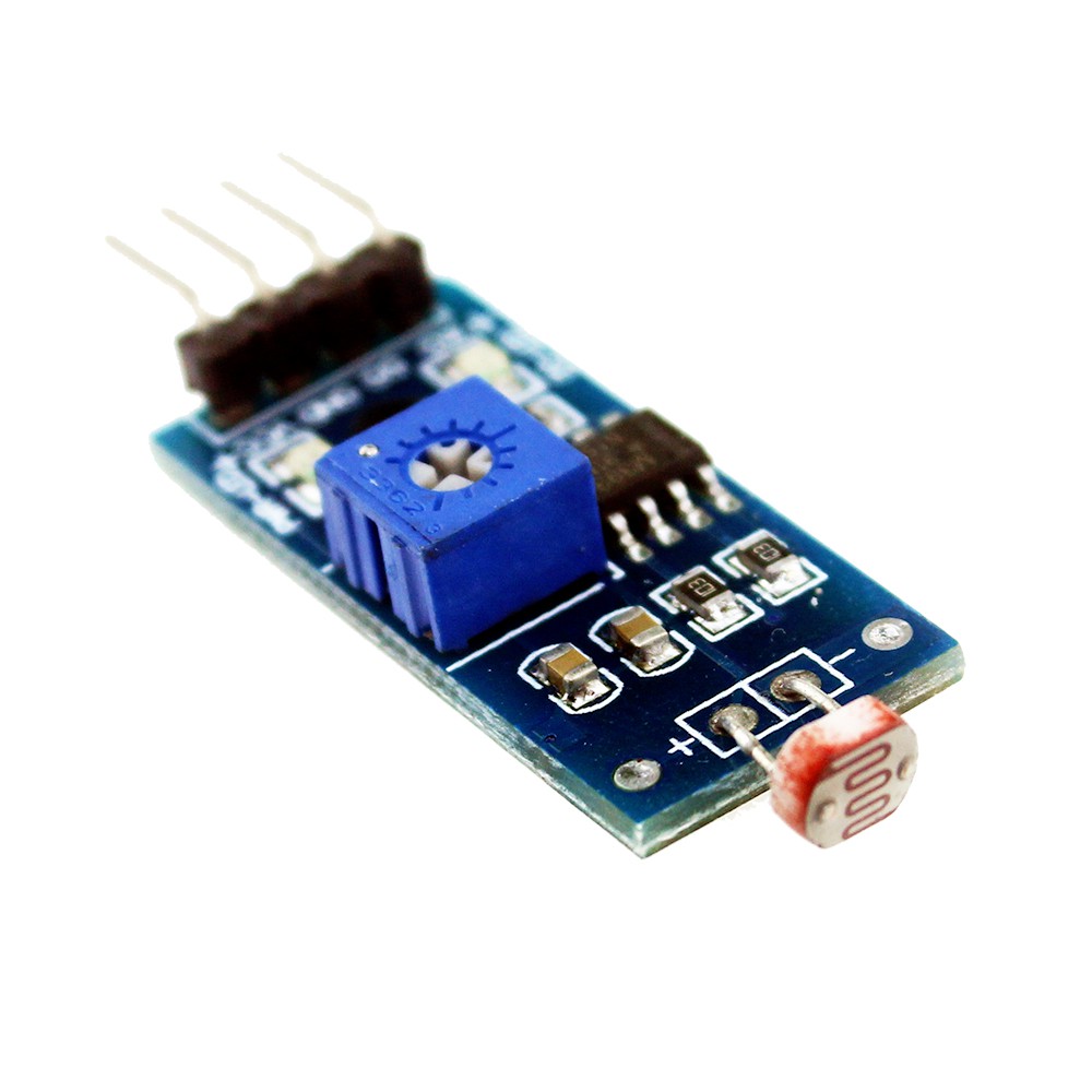
DESCRIPTION:-
LDR sensor is a sensor which is built out of LM393 ic a Light-Dependent-Resistor a variable resistor to trim the values of range of the value given by the sensor to the microcontroller.
Sensor also has an onboard Power led and an onboard Status led which will glow up whenever the sensor senses the light more than the threshold value.
Light-Dependent-Resistor is a type of Resistor which is dependent on the light coming from the surrounding to give the values. It senses the light around it and then sends the signal to the microcontroller.
*NOTE:- AS THIS SENSOR IS A TYPE OF RESISTOR THEN THERE IS A CHANCE OF CERTAIN VARITIONS IN THE VALUES.
This sensor gives the output of DIGITAL and ANALOG type. Difference b/w analog and digital signal is that in the digital signal only high state or low state is given but in the analog signal values b/w 0-1023 is given which is more suitable for condition in the code.
SENSOR SPECIFICATIONS:-

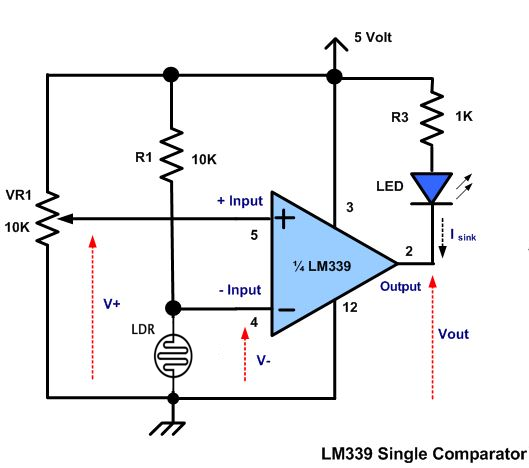
SCHEMATIC DIAGRAM:-
FEATURES AND APPLICATIONS:-
- Light sensitivity is high
- Easy to use
- Adjustable value
- Low price
NOTE:- AS SENSOR IS AMLL SO USE IT CAREFULLY
- Used in smart street lights
- Phones
COMPONENTS NEEDED:-
- Any microcontroller preferably Arduino Uno for beginners.
- A led
- A LDR sensor
- A breadboard
- Jumper wires
- 1kohm resistor
CIRCUIT DIAGRAM:-
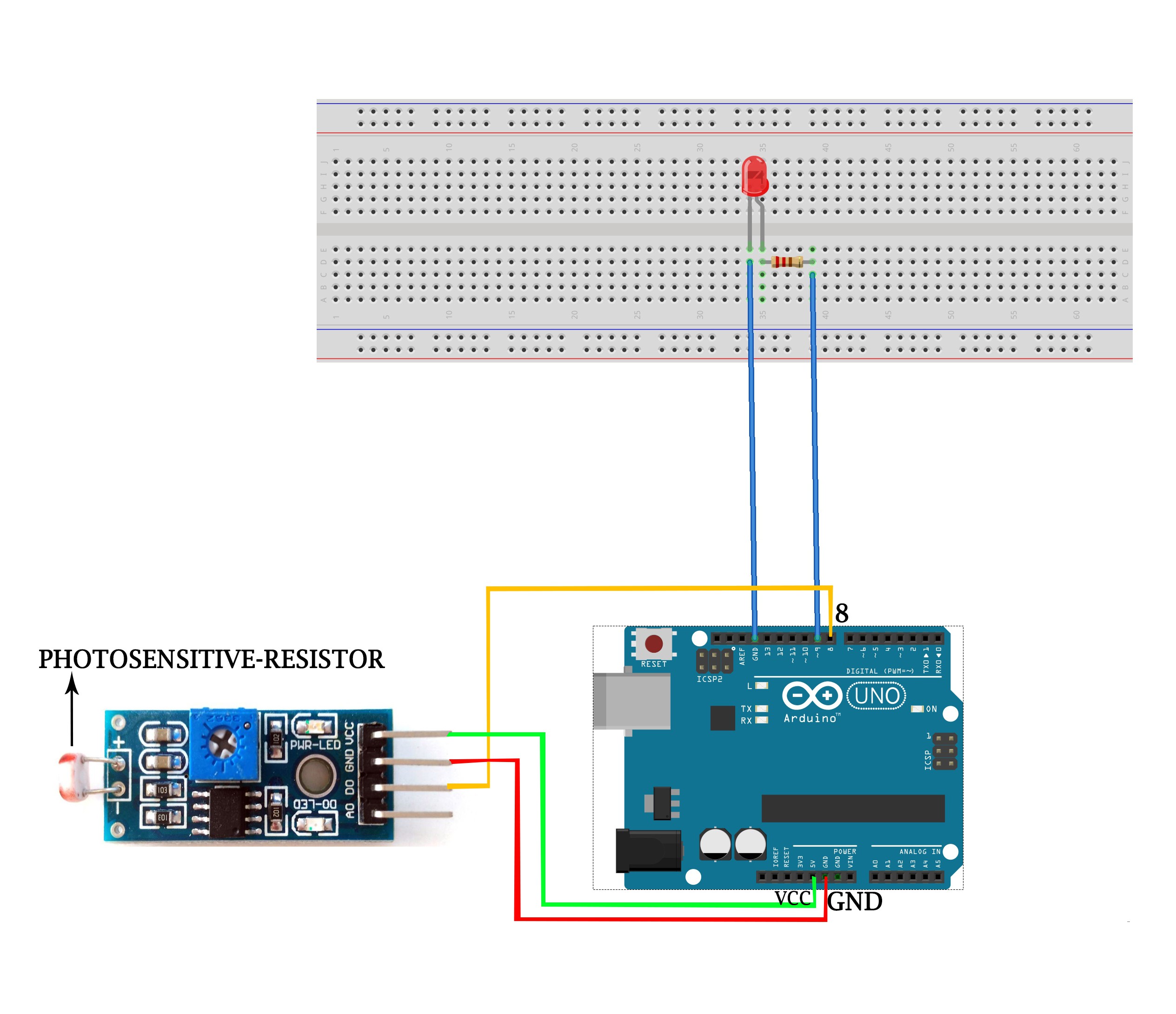
First take the power lines onto the bread board from microcontroller
VCC/5v-->+ line and GND--> - line.
Then connect the sensor on to the bread board and connect power to the sensor from powerlines using jumper wires.
Now connect D0 PIN OF SENSOR TO DIGITAL(PIN 2) OF THE MICROCONTROLLER and AND A0 PIN TO THE A0 PIN OF THE MICROCONTROLLER.
Connect an led to the digital pin 3 of the microcontroller
CODE:-
//put this code in the ide of arduino from this line
//this for digital value
int ldrsensor=2; // initializing the digital pin
int led=3;
int value;
void setup(){
Serial.begin(9600);
pinMode(ldrsensor, INPUT);
pinMode(led, OUTPUT);
}
void loop(){
value=digitalRead(ldrsensor); // reading the digital dat from the sensor
digitalWrite(led, value); // switching buzzer on or off
}
//put this code in the ide of arduino from this line
//note:- this code is for analog value
int ldrsensor=A0; //initializing the analog pin
int led=3; // initializing buzzer pin
int value;
void setup(){
Serial.begin(9600);
pinMode(ldrsensor, INPUT); // assing the pin mode type of the pin as input or output
pinMode(led, OUTPUT);
}
void loop(){
value=analogRead(ldrsensor); //reading the valus from the sensor
value=map(value,0,1023,0,255); // mapping the value from 0 to 1023 b/w 0 to 255
digitalWrite(led, value); //
}
WORKING:-
As the code starts it initializes the pin to which the LDR sensor is connected. As soon as the light dependent changes its resistance from one value to another it send its data then the microcontroller. Then according to the condition in the code the microcontroller turn led on or off.
PCB DESIGNING:-


Now we have got the PCB design and it’s time to order the PCB’s. For that, you just have to go to JLCPCB.com, and click on “QUOTE NOW” button.
JLCPCB are also sponsor of this project. JLCPCB (ShenzhenJLC Electronics Co., Ltd.), is the largest PCB prototype enterprise in Chinaand a high-tech manufacturer specializing in quick PCB prototype and small-batch PCB production. You can order a minimum of 5 PCBs for just $2.
To get the PCB manufactured, upload the gerber file you downloaded in the last step. Upload the.zip file or you can also drag and drop the gerber files.
After uploading the zip file, you’ll see a success message at the bottom if the file is successfully uploaded.You can review the PCB in the Gerber viewer to make sure everything is good. You can view both top and bottom of the PCB.
After making sure our PCB looks good, we can now place the order at a reasonable price. You can order 5 PCBs for just $2 but if it’s your first order then you can get 10 PCBs for $2.
To place the order, click on “SAVE TO CART” button.
My PCBs took 2 days to get manufactured and arrived within a week using DHL delivery option. PCBs were well packed and the quality was really good.
*NOTE:- If you need pcb gor this project than contact me or write me in the comment.
Discussions
Become a Hackaday.io Member
Create an account to leave a comment. Already have an account? Log In.