 danjovic
The idea for this project occurred to me while I was implementing the PC Joystick adapter for #Control Freak , and the user @Dave's Dev Lab mentioned that he had 300 IBM PC jr joysticks and I started to wonder if I could use the cheap Digispark instead of the Arduino Micro.
The PC jr joystick, as most of the early PC controllers provides only a couple of axes and two buttons. In other words only 4 I/Os are necessary and that is exactly what Digispark provides.
I could reuse some of the experience acquired during the development of support for paddles in the Atari adapter for my #AVeRCADE board, as long as I did some work to adapt the "raw" environment of V-USB+GCC to the Arduino "framework" used by Digispark.
First thing done was to synchronize the potentiometer reading to the USB interrupts. That can be achieved by putting the CPU to sleep(), and the timing loop will always run after the CPU wake up to service an interrupt. The header is required though.
Second thing to do is ti turn off Timer1. It took me some time to realize that the Timer 1 (instead of Timer 0) was generating unwanted interrupts, waking the micro controller at the wrong time. Some Arduino functions rely on this timer and therefore will not work, most notably the delay( ) and therefore the Digispark.delay( ).
Main loop code:
void loop() {
  sleep_enable();              // Prepare CPU to sleep
  power_timer1_disable();      // turn housekeeping off
  sleep_cpu();
  sleep_disable();
  if (++interval > 3) {        // run once in row of a three
    interval = 0;
    for (i = 0; i < 150; i++); // 100us delay
    doNewSample();
    populateValues();
    DigiJoystick.update();
  }
}
And the result:

As the USB interrupts occur 8 ms apart, it is easy to count how many times the CPU woke up and run the loop at the desired sample rate, but the least time interval that I could make it work was 1 out 3 which means 24ms.

The sampling loop was written to run as fast as possible. Inside the loop it is necessary to test if the capacitors have charged and each iteration must take exactly the same time.
That was achieved without the use of assembly and the test is performed without the use of the "if" statement. The trick is simple: A variable is initialized at 0 (zero) and added to the state of the bit being tested at each iteration. It is necessary to invert the state of the input bits, though.
While the capacitor is being charged and the voltage at its terminals is under the positive threshold voltage, reading the pin will result into Zero which inverted and mask will become 1 and the variable increments.
After the voltage exceeds Vih, the variable will be added to 0 and will not increment anymore until the end of the counting cycle.
Code is simple as that:
...
aX=0; aY=0; countVar=255
do {
    sample = ~PINB;
    aY += sample & (1 << 0);
    sample >>= 2;
    aX += sample & (1 << 0);
  } while (--countVar);
...
And the result is a counting loop of mere 300us (microseconds)!
The last piece of the puzzle is the calculation of the timing capacitor. The following parameters shall be considered:
Charging time: ~310us
Potentiometer Resistance for maximum charging time: 100k Ohms
Supply Voltage (Vcc): 5Volts
Input threshold voltage: Vih = 2.5VoltsThe calculation formula is well known

The number crushing can be easily done with the aid of Wolfram Alpha

The closest capacitor value is 4.7nF
Buttons
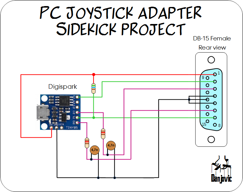
The only two pins left for the buttons are pin 1 and pin 5 and both will require some attention to make them work as button inputs. Refer to the diagram below:

On Digispark boards, digital Pin 1 is pulled down by a 1k Ohm resistor (R2) in series with an LED (D2). One option would be to rework the board and remove the LED or the resistor but another option, less invasive is to use a pull up resistor that provides a resulting voltage above Vih (2.5 as we have seen before) . Tests were performed with 1K and 560 Ohms resistors and both worked fine.
Digital Pin 5 (PB5) is usually configured as RESET in clone boards and if that is the case the board must have its fuses reprogrammed to make the pin work as I/O. That can be accomplished with the aid of a regular Arduino board or a cheap USBAsp clone. That is explained in the links below
- Toivonen's blog - Fixing Pin P5 or 6 on Digispark Clones (using Arduino)
- Digi:Arka project instructions (using USBAsp)
Circuit
The circuit for the adapter is shown below.
Code
The code is pretty straightforward less than 100 lines if you discount the ascii art comments.
/*
  ____  _       _       ____   ____       _
 |  _ \(_) __ _(_)     |  _ \ / ___|     | | ___  _   _
 | | | | |/ _` | |_____| |_) | |      _  | |/ _ \| | | |
 | |_| | | (_| | |_____|  __/| |___  | |_| | (_) | |_| |
 |____/|_|\__, |_|     |_|    \____|  \___/ \___/ \__, |
          |___/                                   |___/

 A Control Freak sidekick project by Danjovic

 Basic release - 14 april 2020

*/


//    _ _ _                 _
//   | (_) |__ _ _ __ _ _ _(_)___ ___
//   | | | '_ \ '_/ _` | '_| / -_|_-<
//   |_|_|_.__/_| \__,_|_| |_\___/__/
//
#include "DigiJoystick.h"
#include
#include

//                 _      _    _
//   __ ____ _ _ _(_)__ _| |__| |___ ___
//   \ V / _` | '_| / _` | '_ \ / -_|_-<
//    \_/\__,_|_| |_\__,_|_.__/_\___/__/
//
uint8_t aX, aY, fireButtons;
uint8_t interval;
volatile uint8_t i = 0; // used in empty counting loop, must be volatile


//    ___      _
//   / __| ___| |_ _  _ _ __
//   \__ \/ -_)  _| || | '_ \
//   |___/\___|\__|\_,_| .__/
//                     |_|
void setup() {
  pinMode(5,INPUT_PULLUP); // Button 1
  pinMode(1,INPUT_PULLUP); // Button 2
  pinMode(0,INPUT);        // Y axis
  pinMode(2,INPUT);        // X axis
  interval = 0;
}


//    __  __      _        _
//   |  \/  |__ _(_)_ _   | |   ___  ___ _ __
//   | |\/| / _` | | ' \  | |__/ _ \/ _ \ '_ \
//   |_|  |_\__,_|_|_||_| |____\___/\___/ .__/
//                                      |_|
void loop() {

  sleep_enable();              // Prepare CPU to sleep
  power_timer1_disable();      // turn housekeeping off
  sleep_cpu();                 //
  sleep_disable();             //

  if (++interval > 3) {        // run once in row of three
    interval = 0;
    for (i = 0; i < 150; i++); // 100us delay
    doNewSample();
    populateValues();
    DigiJoystick.update(); //
  }
}


//     __              _   _
//    / _|_  _ _ _  __| |_(_)___ _ _  ___
//   |  _| || | ' \/ _|  _| / _ \ ' \(_-<
//   |_|  \_,_|_||_\__|\__|_\___/_||_/__/
//


//
inline void populateValues() {
  // populate values
  DigiJoystick.setX((byte) aX);
  DigiJoystick.setY((byte) aY);
  DigiJoystick.setXROT((byte) 0x80);
  DigiJoystick.setYROT((byte) 0x80);
  DigiJoystick.setZROT((byte) 0x80);
  DigiJoystick.setSLIDER((byte) 0x80);
  DigiJoystick.setButtons((uint8_t)fireButtons, (uint8_t)0);
}

//
void doNewSample(void) {
  uint8_t sample,countVar;

  // Release capacitors to charge
  DDRB &= ~( (1<<0) | (1<<2) ) ;

  // now count time it takes for each input to flip HIGH
  aY = 0; aX = 0, countVar=255;
  do {
    sample = ~PINB;
    aY += sample & (1 << 0); //
    sample >>= 2;
    aX += sample & (1 << 0);
  } while (--countVar);

  // reset external capacitors
  DDRB  |=  ( (1<<0) | (1<<2) ) ;  // pin as outputs
  PORTB &= ~( (1<<0) | (1<<2) ) ;  // write zero to output

  // Update the buttons
  fireButtons = 0;
  if (~PINB & (1<<1)) fireButtons|=1;
  if (~PINB & (1<<5)) fireButtons|=2;
}
Prototype
The prototype was assembled and tested using an auxiliary diy adapter board. Initially it was connected to a logic analyzer

Then it was intalled on a proto-board altogether with the other components (nevermind the mess on my table I was in a hurry to take the picture)

And it worked really nice! The Joystick range in both axes stood exactly into the 0-255 range.
Fine Tuning
If the value read on the calibration screen when the joystick is moved at the extremes of its axes (full Down, full Right) is much below 255 then try to change the capacitor to 5,6nF. On the opposite hand if the value reaches 255 much before the position of the axes are on the extremes, the capacitor can be changed to 3.9nF.Joystick calibration screen

PCBs
I have designed two PCBs for this project. One is for the PC-Jr connector and another for a standard DB-15. Both have been shared on OPSPark (PCJr) (DB-15) but are also available in GitHub.
PC Jr board was designed so the Digispark module can be soldered very close to the board.

The standard DB board was designed to be single sided and therefore can be made at home with toner transfer method, for instance.

Discussions
Become a Hackaday.io Member
Create an account to leave a comment. Already have an account? Log In.
awesome! looking forward to trying it out!
Are you sure? yes | no
And I will be happy to see the results :)
Are you sure? yes | no
let me know when you are ready for me to ship you a joystick!
Are you sure? yes | no