 Crazy Circuits
This article shows you how to make a simple three transistor oscillator. The circuit is turning on time delay cascading transistors and LEDs.

An oscillator can be made from:
- one, two or three transistors (BJT, JFET, MOSFET or UJT),
- 555 timer (https://en.wikipedia.org/wiki/555_timer_IC),
- 8038 Integrated Circuit: https://en.wikipedia.org/wiki/Intersil_ICL8038,
- operational amplifier (https://en.wikipedia.org/wiki/Schmitt_trigger oscillator),
- relay,
- DC or AC motor/generator.
The circuit made in this article is known as a Ring Oscillator:
https://en.wikipedia.org/wiki/Ring_oscillator
You can see the circuit working in this video:
Step 1: Design the Circuit
I have drawn the circuit in the old PSpice Student edition software:

The software did not have LED components. Thus I used general purpose diodes. Keep in mind that this could have affected my simulations because general purpose diode voltage is 0.7 V and LED voltage is 2 V.
Calculate the maximum base current:
IbMax = (Vs - Vbe) / (Rc3 + Rb1a + Rb1b)
= 3 V - 0.7 V / (12000 ohms)
= 2.3 V / 12000 ohms = 225 uA
Calculate the minimum collector current for maximum base current:
The minimum collect current is for minimum current gain, Beta:
IcMin = IbMax * BetaMin = 225 uA * 20 = 4.5 mA
Calculate the equivalent collector to ground resistance.
Since the LED voltage does not increase about 2 V the maximum LED current is about:
Iled = (Vs - Vled1) / Rd1 = (3 V - 2 V) / 100 ohms = 10 mA
Therefore the equivalent LED resistance will be:
Rled1 = 2 V / 10 mA = 200 ohms
The transistor will be powering an equivalent collector to ground resistance of:
Rceq1 = Rc1 * (Rd1 + Rled1) / (Rc1 + Rd1 + Rled1)
= 10000 * (100 + 200) / (10000 + 100 + 200)
= 291.262135922 ohms
Will the transistor saturate?:
Icmax = Vs / Rceq1 = 3 V / 291.262135922 ohms = 10.3 mA > 4.5 mA
That means that the transistor will saturate if the minimum current gain (Beta) is above assumed value of 20. We can raise the collector current by increasing the supply voltage. However, this will not be necessary because the LEDs will burn fail. You can raise the supply voltage if you increase the value of the Rd resistors. This is how you calculate the Rd value:
Rd = (Vs - Vled) / Iled
= (3 V - 2 V) / 10 mA = 100 ohms
Calculate the maximum and minimum time constants:
The capacitor is considered to be fully charged after 5 time constants.
The maximum time constant is at maximum resistance seen by the capacitor. This occurs when when transistor is OFF.
T1 = (Rceq1 + Rb1a) * C1
= 0.60689320388 seconds
The minimum time constant is at minimum resistance seen by the capacitor. This occurs when the transistor is ON:
The transistor input can be modelled as an equivalent resistance:
(https://forum.allaboutcircuits.com/threads/small-diode-emitter-resistance-re.59624/)
re = 26 mV / IeBias
= 26 mV / IcMax
= 26 mV / 10.3 mA
= 2.52427184466 ohms
rbeMin = re * Beta = 2 * 20 = 50.4854368932 ohms
rbeMax = re * Beta = 2 * 500 = 1,262.13592233 ohms
T2min = (Rceq1 + Rb1a)||(rbeMin + Rb1b) * C1
= 0.27224645381 seconds
T2max = (Rceq1 + Rb1a)||(rbeMax + Rb1b) * C1
= 0.41443762164 Seconds
The frequency of oscillations can be highly influenced by the transistor current gain for another reason, if the current gain is low. It is the current gain that affects transistor the output and thus the oscillation state (ON or OFF) of the next cascade transistor.
Calculate the maximum capacitor voltage:
The capacitor can only reach its maximum voltage if the feedback loop is disconnected. The LED will be OFF and its equivalent resistance (Rled + Rd1) will be near infinity. The transistor is a current source. Therefore:
Vc1Max = (Vs - Vbe) / (Rc3 + Rb1a + Rb1b) * Rb1b + Vbe
= 2.3 V / 12000 ohms * 1000 ohms + 0.7 V = 0.89166666666 V
From the formula above you can see the purpose of the Rc1 resistor, that is allowing the capacitor charging even after the LED1 is off.
Step 2: Simulations
The distance between the two maximums of green and red square waves is about 300 mSeconds.

This is less than the predicted time constant of about 900 mSeconds to 1 second. That is because transistor model in the simulations has a high current gain and transistors are turning ON earlier. You need to remember that high current gain transistors can turn ON if capacitor C1 voltage, Vc1 exceeds 0.7 V (well below the maximum capacitor charging voltage of 0.89166666666 V) and this could be well before the capacitor is fully charged to its maximum voltage value. The LED changing frequency fc = (1/600 ms) = 1.66666666667 Hz. We can also calculate the total frequency of the oscillator. The period seems to be 300 ms * 3 = 0.9 seconds (from the graph). Therefore the oscillation frequency is fo = 1/0.9 seconds = 1.1111111111 Hz.
Step 3: Make the Circuit
I did not use a soldering iron. I twisted the wires together with pliers.
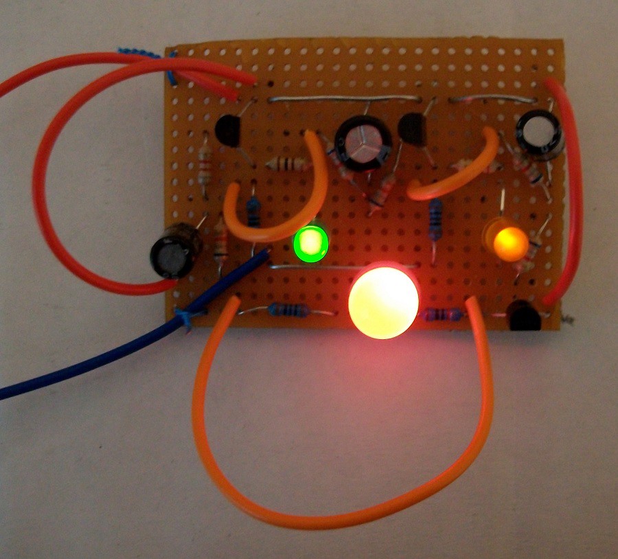
LED1: Green, LED2: Orange, LED3: Big clear red
Discussions
Become a Hackaday.io Member
Create an account to leave a comment. Already have an account? Log In.