 Super Circuits
This article explains how you can build a small signal motor driver. A signal is entering the input of the circuit and is amplified with three transistors to drive a low current motor.
This circuit can be connected to an AC amplifier. The AC amplifier can be connected to a sensor that could be a:
- microphone,
- ultra-sonic sensor,
- infrared sensor,
- antenna.
Thus this circuit can cause the motor to move due to:
- sounds,
- ultra-sonic waves,
- infrared remote control transmission,
- radio waves.
I thought of the circuit fin this article after looking at the following Instructable:
https://www.instructables.com/id/Transistor-Light-Dimmer/
It is important to mention that the circuit can be implemented with just one MOSFET transistor. However, well-known MOSFETs are rare, MOSFETs cost more money and you might need to look for a MOSFET in your workshop inventory. Also, the MOSFET transistor would not allow you to control the current magnitude that controls the motor speed. In the circuit shown, the greater the magnitude of the input signal the faster the motor will spin. However, you can still control the speed of the motor with MOSFETs and Pulse Width Modulation (PWM) inputs: https://diyelectronics.webs.com/circuits.htm
Step 1: Design the Circuit
I have drawn the circuit in PSpice student edition version 9.1 software:
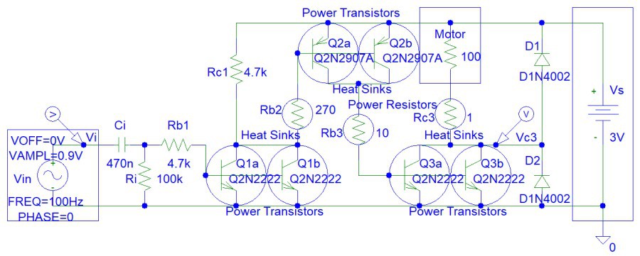
Calculate the maximum output current at worse case scenario. At worse case scenario transistor current gain, Beta = 20.
Ib1 = (Vin - Vbe3) / Rb1 = (3 V - 0.7 V) / 4.7 kohm = 2.3 V / 4700 ohms = 489.3617 uA
Ic1 = Ib1 * BetaMin = 489.3617 uA * 20 = 9.78723404 mA
Ib2 approximately equals to Ic1 because very little current is flowing through Rc1 resistor.:
Ic2 = Ic1 * BetaMin = 9.78723404 mA * 20 = 0.19574468085 A
Ic3 = Ic2 * BetaMin = 0.19574468085 A * 20 = 3.91489361702 A
Rc3 is 1 ohm and the transistor does not need to saturate. The maximum current is actually not 3.91489361702 A, but Vs / Rc3 = 3V / 1 ohm = 3 A < 3.91489361702 A (occurs when the motor is a short circuit if its movement is mechanically impeded or stopped), because the transistor saturates. However, you can achieve 3.91489361702 A output current if you raise the supply voltage to 4 V.
Now we can calculate the other resistors.
Rb2 = (Vin - Vbe2) / Ib2Max = (3 V - 0.7 V) / 9.78723404 mA
= 2.3 V / 9.78723404 mA = 235 ohms < (Rb2 || Rc1) = (270 ohms || 4700 ohms)
Rb3 = (Vin - Vbe3) / Ib3Max = (3 V - 0.7 V) / 0.19574468085 A
= 2.3 V / 0.19574468085 A = 11.75 ohms approximately 10 ohms
Rc1 and Ri resistors ensure that the circuit and the motor is OFF when the circuit is disconnected or when no input signal is applied.
Step 2: Simulations
Simulation show high circuit gain:
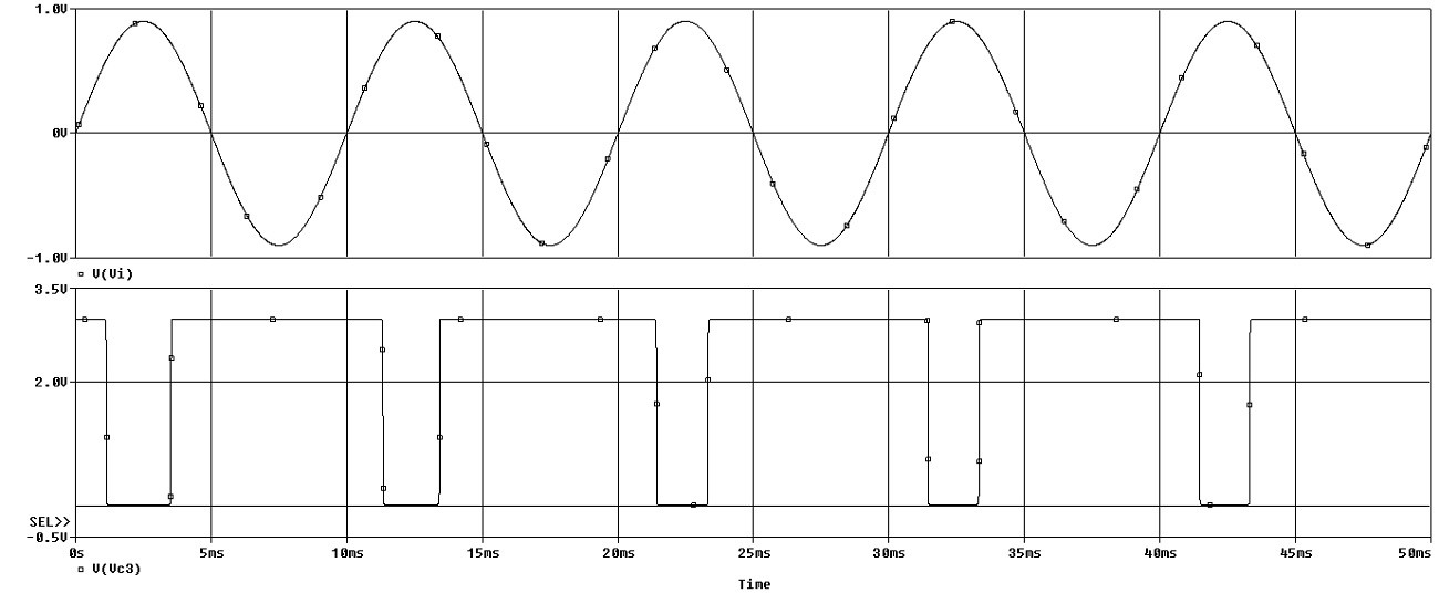
You can see that the output transistor (Q3a and Q3b pair) is still saturated even when the input signal is only 1 V. Thus the minimum input signal is 1 V.
Discussions
Become a Hackaday.io Member
Create an account to leave a comment. Already have an account? Log In.